Sharper Image iPulse SI325 Auxiliary Input Replacement
ID: 19163
Description: This guide will demonstrate how to replace the...
Steps:
- Gently position the device so that the buttons and speakers lie face down.
- Unplug the power cord from the "DC Input."
- Remove the four 12mm phillips head #2 screws located along the outer edge of the white case.
- Be careful! There are two small, easily-broken, plastic tabs at the bottom of the device keeping it together.
- Once you remove the screws, pick the device up so that the grey label on the bottom of the device faces toward you.
- With your thumbs on either side of the grey label, slowly push with both thumbs until the case pops open.
- A small gap will open as the two tabs are released.
- Do not pull the two halves apart yet. They are held together by the speaker wire.
- Grip both sides of the top round part of the case and carefully open it like a clam. The bottom of the two halves are connected by the speaker wire. Do not separate by more than 1 centimeter.
- Grip either side of the top round part of the case and carefully open the device to reveal all the hidden treasures inside!
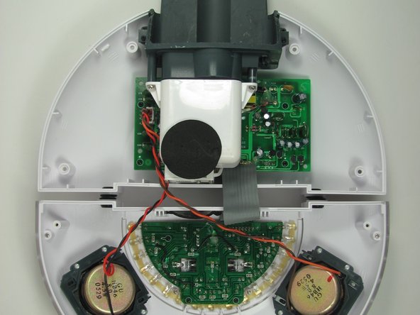
- Lay the device down, so that all the internal components are facing upwards.
- Turn the device over so that the internals are facing down; the Light Intensity Dial will be facing you.
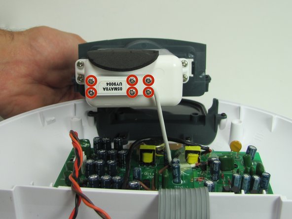
- Remove the three 7mm Phillips #1 screws connecting the Zipconnect unit.
- Turn the device over again so you are looking at the internals.
- The Zipconnect unit will lift out but will still be attached by a wire connected to the motherboard.
- Remove the six 7mm Phillips #1 screws attaching the Zipconnect unit to the motherboard wire and set the unit out of the way.
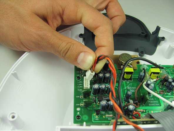
- Next, disconnect the speaker wire from the motherboard by gripping the wires as close to the connection as possible and pulling the connector out.
- Moving the connector back and forth as you pull will make removal easier.
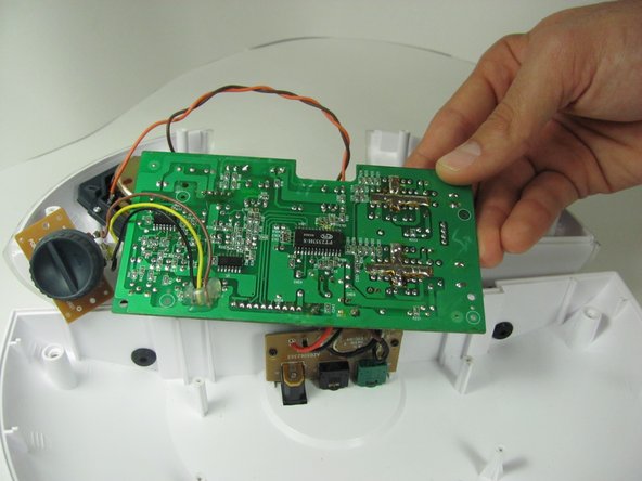
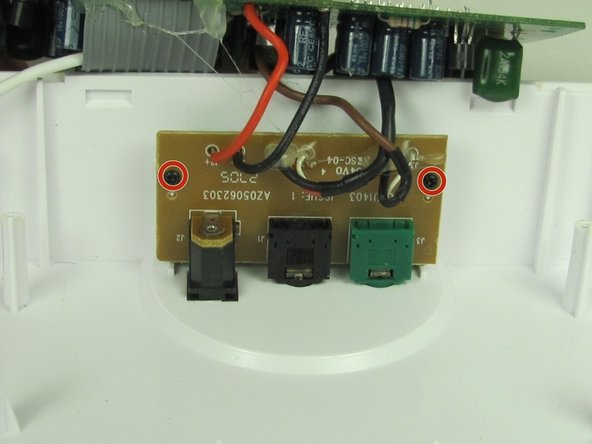
- Remove the two 11mm Phillips #1 screws attaching the small brown circuit board to the plastic case.
- Also remove the four 11mm Phillips #1 screws attaching the motherboard to the plastic case.
- Lift up on the motherboard and light intensity dial circuit board to expose the circuit board containing the auxiliary input, sub input, and DC input.
- Remove the two 7mm Phillips #1 screws attaching the brown circuit board with all of the inputs.
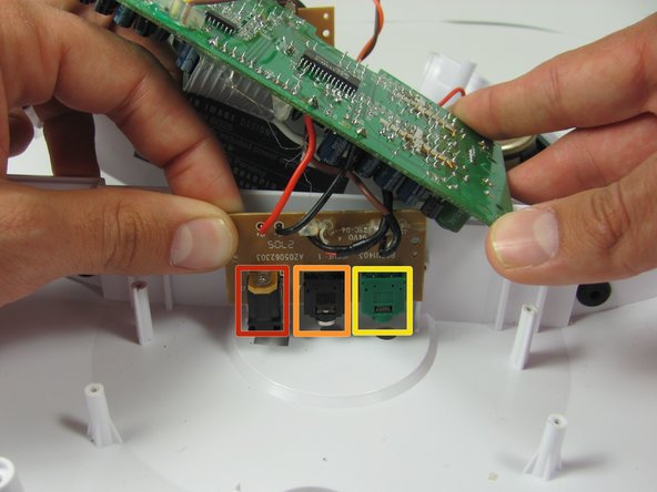
- Lift up the circuit board containing the Auxillary, DC, and sub inputs and move the lower case out of the way.
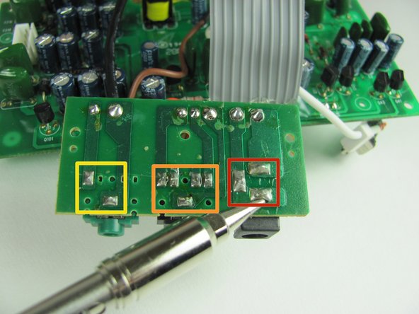
- Turn the circuit board over so the solder is visible. Depending on which input is broken remove the solder connecting either the Auxillary, DC, or Sub input.
- DC input
- Auxillary Input
- Sub Input