Acer Aspire E1-571G Thermal Paste Replacement
ID: 192045
Description: Hello everyone, in this guide Ill be showing...
Steps:
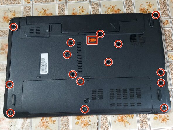
- Remove all the shown screws, slide out the battery and DVD drive. The screws marked in RED are M3.0x8.0.
- Remove the Wi-Fi mini PCI card (marked in blue) and the SSD.
- Remove the screws marked in GREEN (M2.0x3.0) and YELLOW (M2.5x5.0).
- Here you can upgrade the RAM and SSD before finishing.
- Use a prying tool to release all the clips and remove the palmrest.
- In my guide I will NOT be removing the keyboard, because I was able to connect and disconnect the connectors regardless. For you, it may be recommended. There are 3 connectors that need to be unplugged (power switch, mousepad, keyboard).
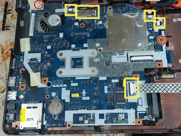
- Remove the 2 screws that hold the motherboard in place.
- Disconnect all the marked connectors.
- Carefully lift the motherboard from the DVD connector, flip it, disconnect the power connector and slide the motherboard out.
- Unscrew the heatsink (RED).
- Unscrew the fan (GREEN) and disconnect it.
- Clean the old thermal paste both from the cooler and the CPU+GPU. It is best to use isopropyl alcohol and cotton swabs or paper towel, but be careful not to go too hard on the CPU+GPU.
- When the fan is removed, it can be opened by unscrewing the 4 screws that hold it together, for further cleaning. When putting it back together, be vary careful while tightening those, because the plastic is very fragile.
- It is also recommended to use compressed air to remove any dust in the laptop case itself.
- Here you can upgrade the CPU if you want.
- Don`t use too much thermal paste, just enough to cover some portion of the pad. If you have a spreader, use it. The thermal paste will apply evenly after you tighten the heatsink.
- Last, put the heatsink back carefully and tighten the screws in order to ensure even pressure.
- Don`t forget to plug in the fan connector!