HTC One Display Assembly Replacement
ID: 19277
Description:
Steps:
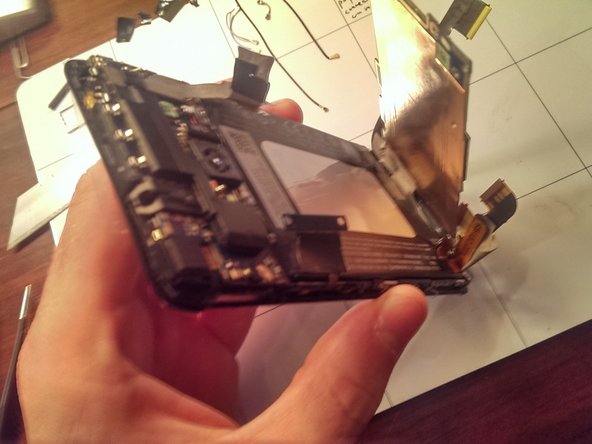
- The entire phone is built upon the screen assembly so in order to replace the screen assembly you must disassemble the entire phone and then build it back up on top of a new screen assembly
- The touch screen and LCD display are fused together so it is very difficult to replace one piece or the other separately. In order to be successful, it is recommended to replace the entire assembly.
- Remove the SIM card and tray by ejecting it with a paper clip or SIM Ejector Tool
- Removing the rear alluminum case is the hardest part of repairing the internals of the HTC One. In many blogs/videos the backing is damaged so its worth buying a spare one for this repair just in case theres damage.
- The unit I've got was already popped open.
- A contributor found it easier and minimal damage to get into the case by prying inside the sim card slot area first and then working their way around with guitar picks.
- Additional videos that might also help with this process:
- http://youtu.be/qZFAsgjCunc
- http://www.youtube.com/watch?v=cyrxa23Ow...
- After you have removed the rear aluminum case for the first time and broken that adhesive, the back case will come on and off easily using the plastic pry tools
- Remove the three pieces of black electrical tape using an exacto knife or razor blade
- There is a lot of black electrical tape and silver colored tape to remove throughout the process
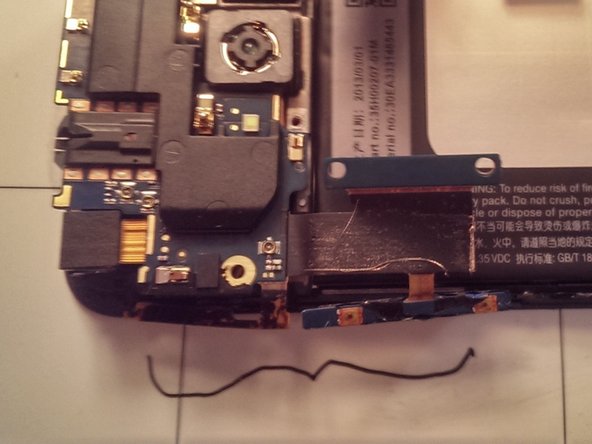
- The black coaxial cable that runs near the gray and blue cable is present only in certain models. This phone in the picture is the Sprint model and has CDMA antennas that will be in addition to GSM phone models.
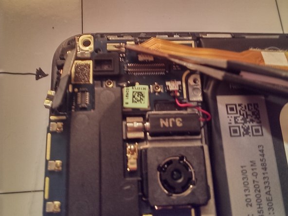
- Remove the five coaxial cables using tweezers
- They are easy to pop out by applying a little pulling pressure
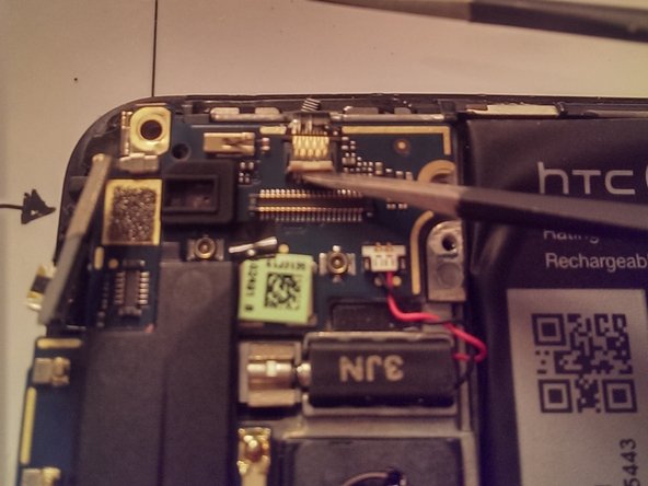
- In order to remove the motherboard, the flex cables must be demated
- First remove the four flex cables indicated with arrows. Some of the metallic colored tape will need to be peeled back in order to access these.
- The flex cables are held in place using ZIF (zero insertion force) connectors.
- For the top two and the bottom left (in the photo) the black tab needs to be carefully opened using a plastic prying tool in order to remove the flex cable.
- For the bottom right connector, the white tab needs to be carefully lifted up with a plastic prying tool in order to release the flex cable.
- Using a Philips #000 screwdriver unscrew the connectors indicated from the mother board
- After the screws have been removed, the connector will need to be detached from the mother board using a plastic prying tool.
- Using again the Philips #000 unscrew the four screws that are holding down the motherboard as indicated in the photo. The screws have already been removed in the photo
- Be sure to organize and label each screw because they are different lengths and will need to be put back in the same hole during reassembly. By the end of this whole process you will have about a dozen different screws.
- Pull the motherboard up from the side shown in the image
- The motherboard is held down on one end with the metallic colored tape and comes up with light pulling with your hand
- Remove the three screws using the Phillips #000 screwdriver as indicated in the photo
- The volume rocker button and another piece are adhered to the body. In order to remove this, heat the adhesive with the hot iOpener tool. Both pieces then peel away easily.
- Disconnect these two pop connectors by gently prying up from the daughterboard with blunt tipped tweezers
- Detatch the flex cable by flipping up on the white portion of the ZIF connector. This releases the flex cable
- Gently pull the flex cable from the connector
- Release the vibrator motor by prying up on the moving end of the motor
- The vibrator motor is connected by two wires to daughterboard and does not need to be detached from the daughterboard, just released from its slot in the housing
- Gently pull the daughterboard from the phone body
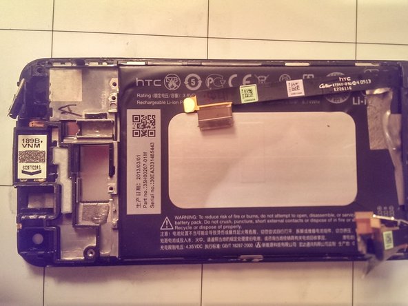
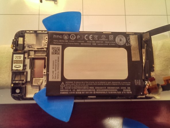
- There is an adhesive holding down the battery. Place the hot iOpener on top of the battery for a minute.
- Then place the iOpener onto the table and place the phone glass against it to heat the adhesive from the other side.
- As the phone is lying on the iOpener, softly pry away the battery using the plastic picks. The battery flexes slightly so pry away gently.
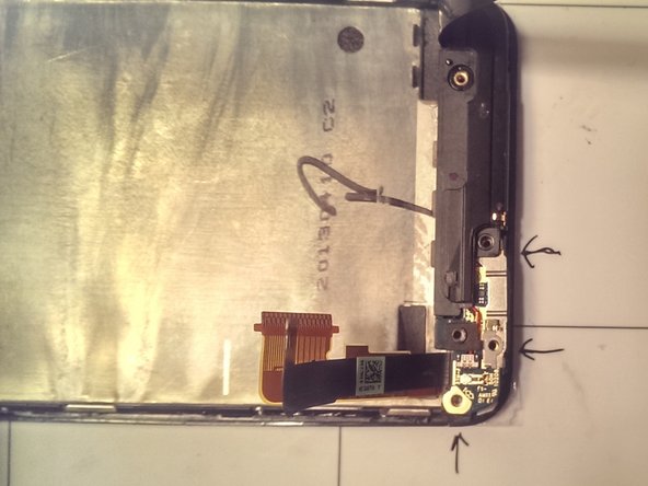
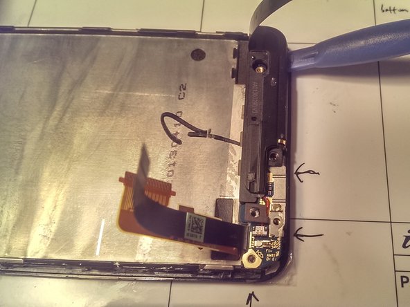
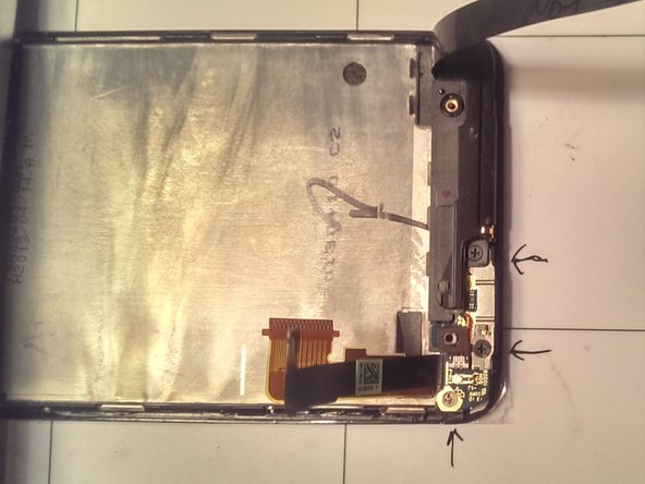
- Remove the three screws indicated
- Remove the loose metal piece
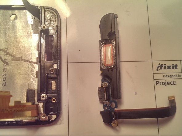
- Pry up the small logic board and attached speaker using a plastic prying tool. It is held down with a little adhesive and tape.
- The small logic board and metal piece are shown here
- This plastic piece goes directly over the screw hole. It falls out easily, but when removing and replacing it only goes back in place in one direction. The shape of the plastic piece makes it go into place in only one direction.
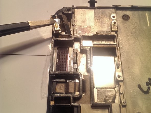
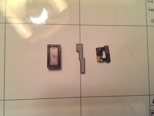
- Remove the earpiece by prying up with a sharp tweezer. It is held in place with adhesive and needs a little prying.
- Remove the power button by Peeling away the small amount of tape holding it to the screen assembly.
- Remove the plastic spacer that looks like a Tetris piece, it slides in and out easily and may fall out if not careful.
- Reassembly entails building everything onto the new screen assembly.
- First transfer the earpiece, power button, and spacer onto the new screen assembly
- Next replace the small logic board that contains the USB connector
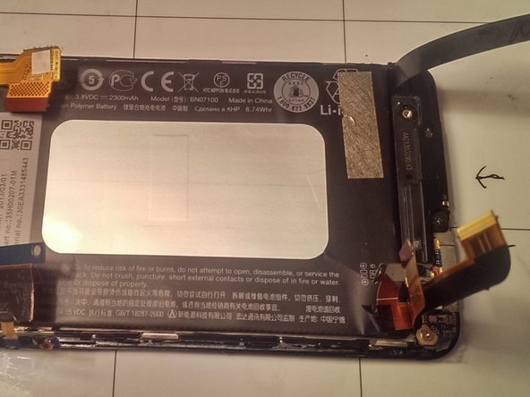
- Put down some double sided tape to hold the battery against the screen assembly
- When putting the battery in place, make sure that the battery's flex cable is facing up and at the correct corner as seen in the photo so that it will be able to connect to the mother board in the later reassembly steps.
- Follow all the steps in reverse to reassemble the phone.
- The image is shown here to illustrate where to put the coaxial cables when replacing them.