Logitech Zone 305 Battery Steps
ID: 193671
Description: Logitech Zone 305 battery steps prereq
Steps:
- Insert the point of an opening pick into the seam between the speaker plate and ear cup.
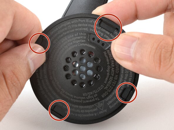
- Slide the pick along the seam to release the four speaker plate clips.
- Don't try to fully remove the speaker plate, as a wire connects it to the ear cup.
- Use your fingers to move the speaker plate towards the right side of the ear cup so you can access the screw.
- Use a Phillips screwdriver to remove the 7.1 mm‑long pancake screw securing the speaker housing.
- This step reattaches the speaker plate temporarily to keep it from wobbling during repairs.
- Align the speaker plate to the speaker housing and squeeze firmly to engage two of the four clips.
- Use your fingers to grab the speaker housing from the back.
- Pull firmly to pop the housing off from its ball joint.
- Be careful not to pull too far—a speaker wire still connects the housing and the ear cup.
- Use a Phillips screwdriver to remove the three 5.3 mm‑long screws securing the midplate.
- Be careful not to strain the speaker and battery cables during this step.
- Insert an opening pick in the seam between the midplate and the ear cup.
- Twist the pick to loosen the midplate.
- Use your fingers to swing the midplate away from the ear cup.
- The battery's lightly adhered to the midplate.
- Slide the tip of an opening pick under the battery and pry gently to separate it from the midplate.
- Use your fingers to peel and remove the foam pad covering the circuit board.
- Store this pad in a clean location for reassembly.
- Use angled tweezers to grip the edges of the battery connector.
- Gently rock the connector side-to-side and slide the battery connector out of its socket.
- This connector can be difficult to disconnect. Squeeze the tweezers close to the tips to help grip the connector.
- Remove the battery.
- The remaining instructions show how to reassemble the headset.
- Cut and attach a small strip of double-sided tape onto the battery.
- Remove the liner to expose the adhesive.
- Use your fingers to slide the battery connector fully into its circuit board socket.
- Place the foam pad over the circuit board and use your finger to press it in place.
- Align the battery in the midplate recess such that the battery cable reaches its circuit board connector.
- Use your fingers to press the battery onto the midplate.
- Swing the midplate back in place over the ear cup.
- Use a Phillips screwdriver to install the three 5.3 mm‑long screws to secure the midplate.
- At this point, you'll need to separate the speaker plate you partially reattached earlier to reinstall the pancake screw.
- Use your fingers to unclip the speaker plate from the housing.
- Align the speaker housing to the midplate such that the speaker wire threads through both parts without twisting.
- Align the ball joint to the speaker housing's center cutout.
- Use your fingers to firmly press the speaker housing onto the ball joint to pop it back in place.
- Use a Phillips screwdriver to install the 7.1 mm‑long pancake screw to secure the speaker housing.
- Use your fingers to move the speaker plate back over the speaker housing.
- The top clip is wider than the rest of the clips. Use this to help align the speaker plate to the housing.
- Use your fingers to squeeze and engage the four clips to secure the speaker plate to the housing.