Rival Mini Chopper MC-67BL Motor Replacement
ID: 19379
Description: This guide will help you remove the motor and...
Steps:
- Twist the plastic lid counterclockwise to unlock it.
- Lift the lid to remove it from the container.
- Carefully remove the blade from the container.
- For reassembly, the teeth on the metal shaft line up with slots on the inside of the plastic hole.
- With your hand, twist the container counter-clockwise until it unlocks from the base. Remove the container by lifting it straight up.
- Use your fingers to pry out the two rubber feet from the bottom cover of the base.
- The two feet furthest from the button tower contain screws. The other two feet do not.
- Use the Phillips #2 screwdriver to unscrew the two 12.7-mm screws underneath the rubber feet.
- Use the same screwdriver to unscrew the 15.88-mm screw from the back of the chopper.
- Firmly lift the bottom cover off of the base.
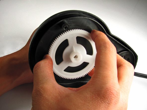
- Remove the smaller white gear by lifting it up with your hand.
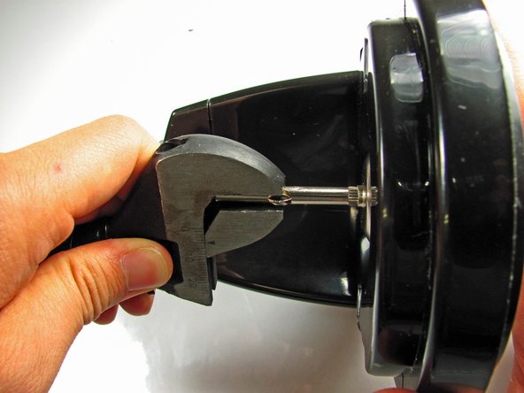
- Use a pair of pliers or any other clamping tool to securely hold the blade-shaft that sits above the base.
- Grab the gear with your other hand and turn CLOCKWISE. Unlike most screws, the gear is reverse-threaded to allow the blade to spin.
- Continue turning the gear until completely removed from the blade-shaft.
- Pull the shaft from the base.
- This will require a bit of force.
- Use a Phillips #2 screwdriver and unscrew the two base screws.
- Unwind the power cord from the base pegs.
- Use the plastic opening tool to pry open the base from the main body.
- These two plastic prongs are pressed fit into the base. It may take some effort to pry the base completely off.
- Once freed, lift the base panel from the main body. The motor and power cable are connected to this panel.
- Use a Phillips #2 screwdriver to remove the screws that attach the motor to the base.
- Pull the power cord wires up from underneath the wire hook on the side of the motor.
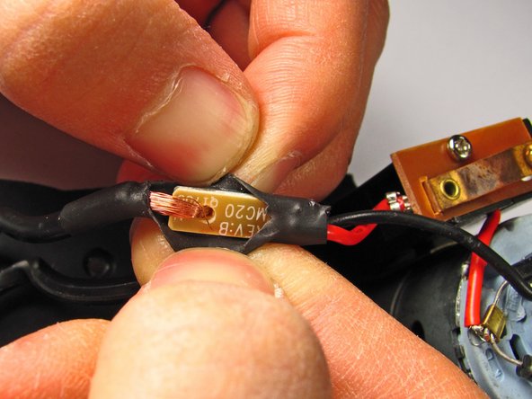
- Carefully cut into the black wire casing for both wires using a small knife, and peel away the black casing.
- Only cut deep enough to remove the casing.
- For reassembly you will need black electrical tape to keep the wires from being exposed.
- Use a soldering kit to remove solder from the circuit board for the red wire.
- Follow this soldering guide if you need extra help!
- Use a small knife to cut the copper wires from the bracket holding the black wire and power cord together.
- For reassembly the copper wires will need to be soldered together.
- Use a Phillips #1 screwdriver to unscrew the single 4.76-mm screw from the motor base to finish removing the motor.