Razer Leviathan V2 X Disassembly Guide
ID: 193898
Description: Repairability rating 8/10. Easy for beginners,...
Steps:
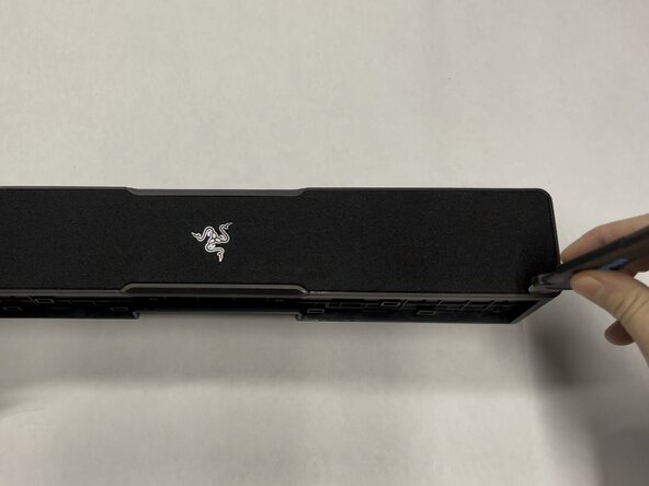
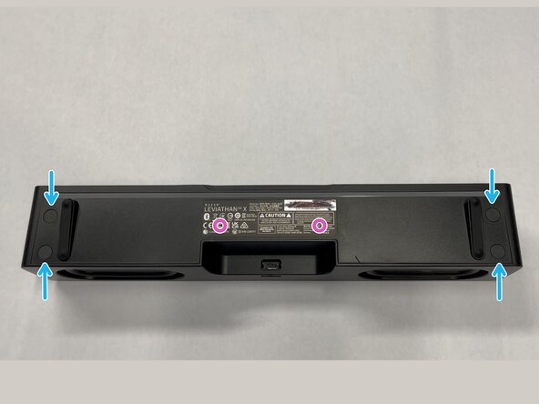
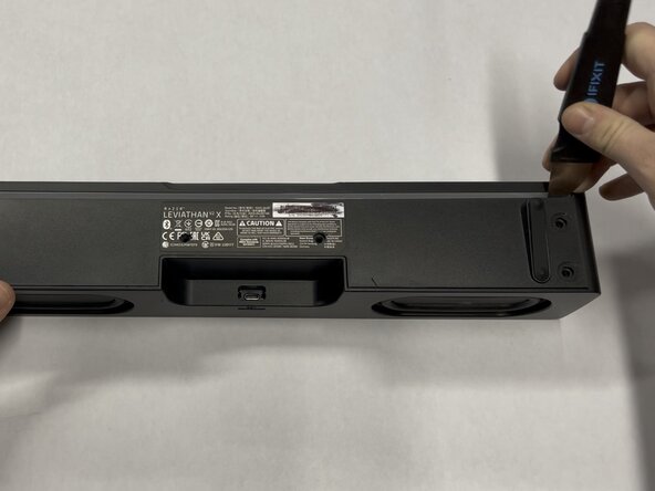
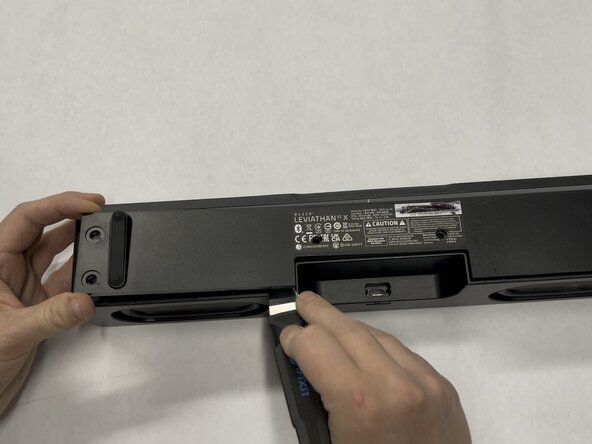
- Using a flat metal "Jimmy" tool, gently work out the front metal screen and mesh.
- Insert the tool vertically ~3-5mm (~1/8-1/4in), then pry gently away from the mesh screen. The screen should slowly start to come out directly vertical.
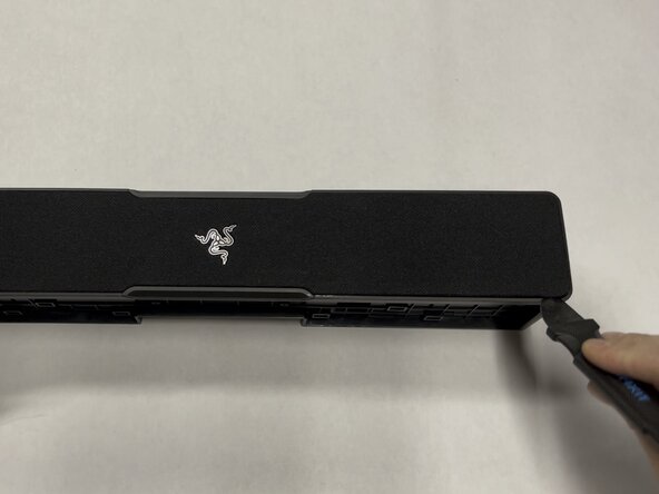
- Repeat this every few cms/inches, working in a loop around the outside edge one or two times until you get the metal/mesh screen off.
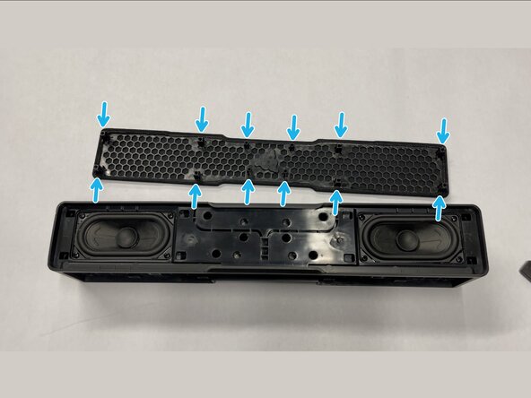
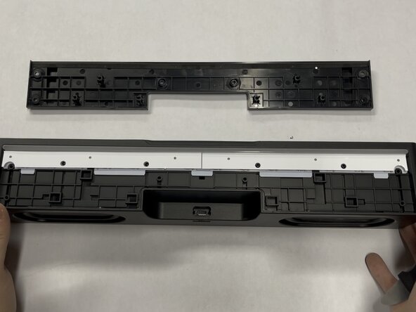
- On the bottom of the metal/mesh screen there are 12 protruding plastic tabs that are inserted ~2cm into the body of the speaker.
- It should come directly vertically up with very little to no pressure if you get the tool angle just right. Be patient, and work slowly.
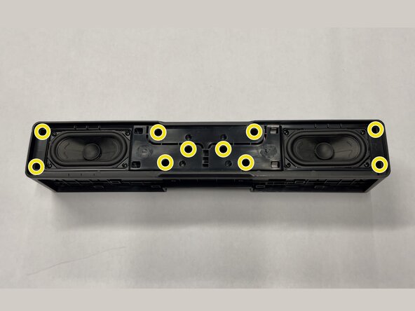
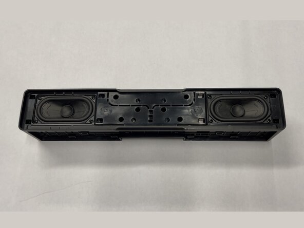
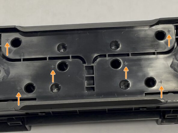
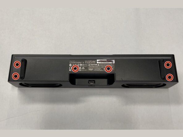
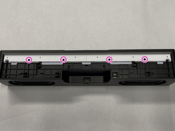
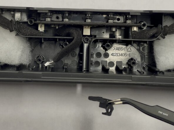
- Use a Philips #2 screwdriver to remove the ten 14 mm-long screws mounting the inner frame to the body.
- Note: There are helpful plus sign/star symbols next to each hole that has a screw in it! See the third image, they look similar to this: ✦
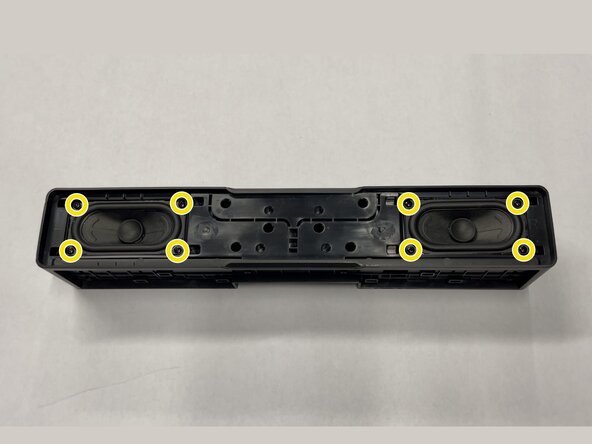
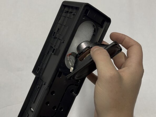
- Use a Philips #2 screwdriver to remove the eight 14 mm-long screws holding in the two speakers.
- These screws are the same size as the screws from the previous step
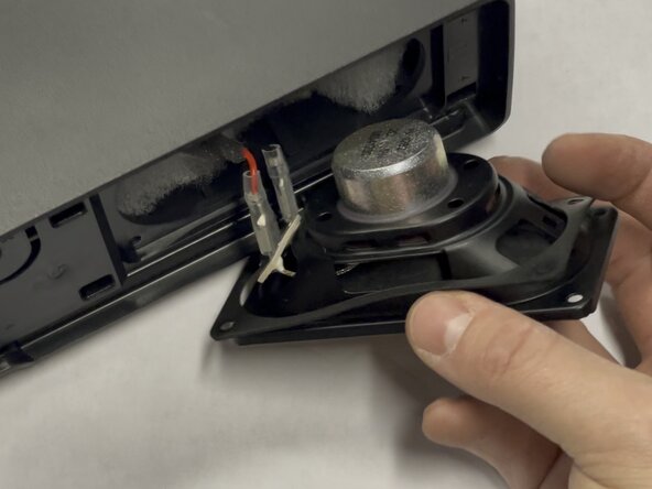
- Lift the speaker from the body to get at the wires.
- Make sure to keep the thin gasket with the speaker for vibration isolation.
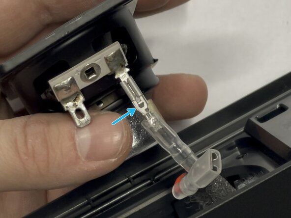
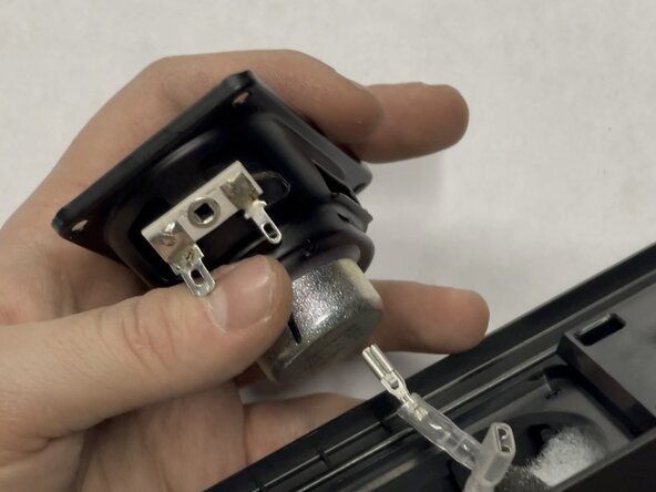
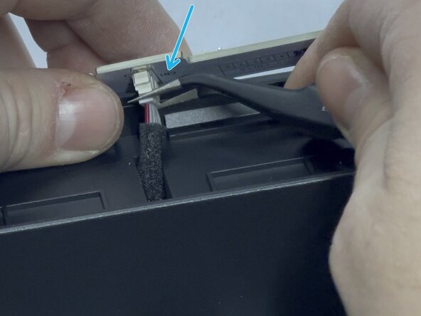
- Slip the plastic cover downward off the connector
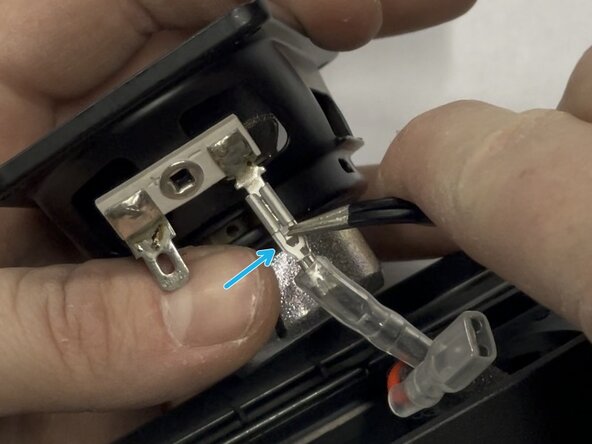
- Use metal tweezers or a tiny driver bit to press down the tab in the center of the connector.
- Gently pull downward on the connector to disconnect it from the body.
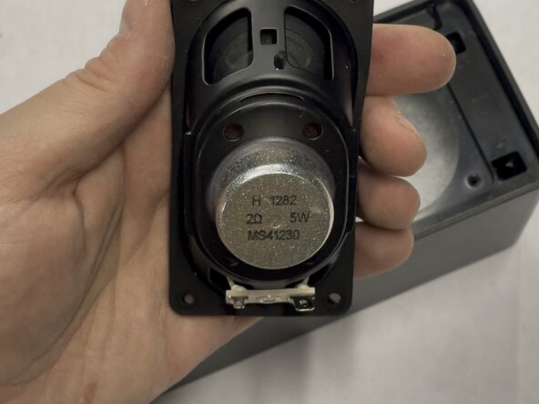
- Remove each of the two speakers and set them aside.
- Speaker Details: 2″×4″ 2Ω 5W speaker (MS41230)
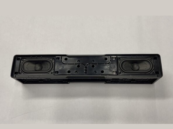
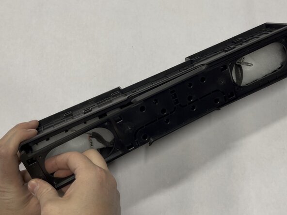
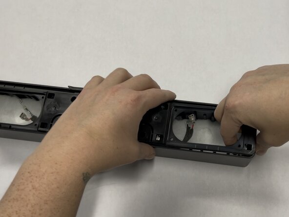
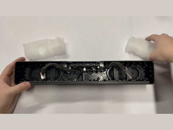
- Pull on each side of the inner plastic frame vertically to slide it out of the body.
- If you have to apply force, first re-verify that you have removed all 18 screws from Steps 2 and 3.
- You can use the speaker holes as handles to grip the frame.
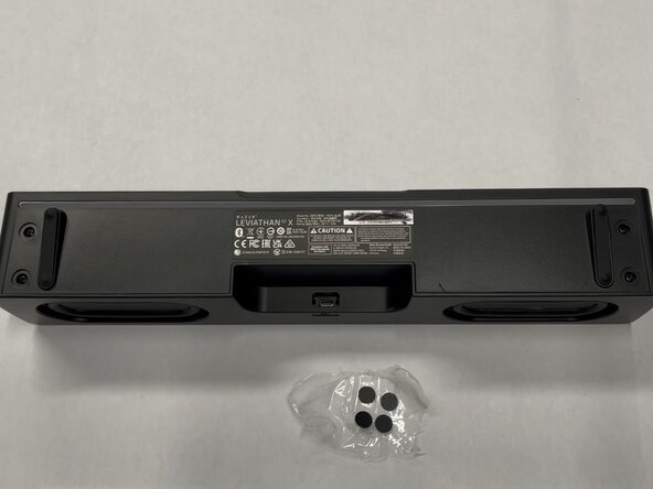
- Remove the 4 sticky screw covers from the bottom of the speaker
- Tip: Place these on clean plastic or wax paper and you will be able to easily reuse them, but we suggest tossing them and showing off the screws after reassembly!
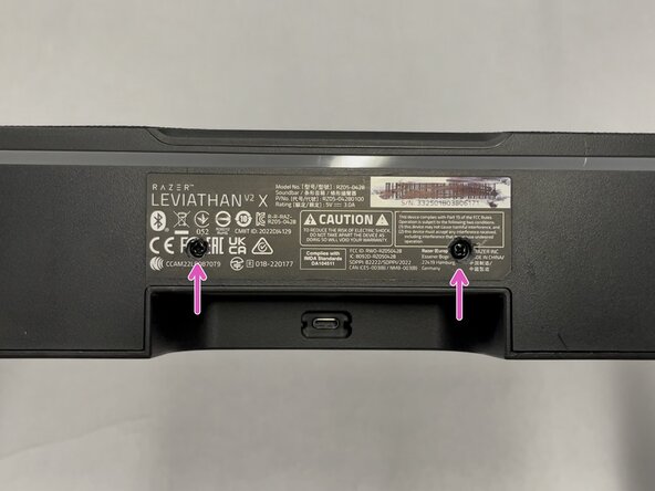
- Use a Knife to cut through the sticker to reveal two more hidden screws. See image #3
- Use a Philips #2 screwdriver to remove the six 10 mm-long screws holding the bottom cover in place
- Use the Jimmy tool to remove the bottom cover, again working slowly around outside of the part. It should come off with little force needed.
- If you have to use force to remove bottom cover, re-verify you have removed all six of the screws!
- Use a Philips #1 screwdriver to remove the four 8 mm-long screws holding in the RGB diffuser and board
- Note: For this step you need a smaller screwdriver than all of the other steps.
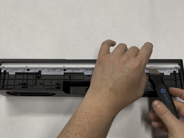
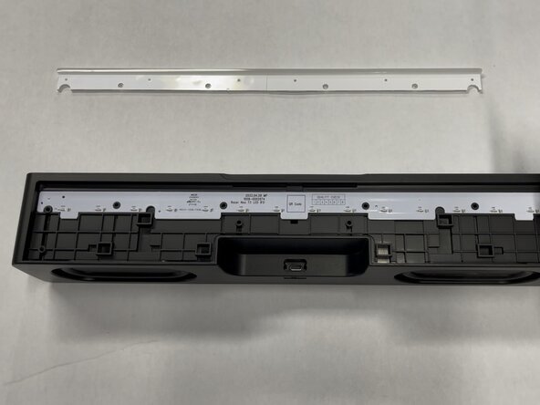
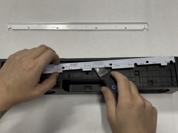
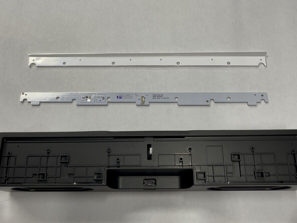
- Slip Jimmy tool between the light bar diffuser and PCB then lift gently upward, then remove the light bar diffuser and set aside
- Gently pry the RGB board free using the jimmy tool and lift it upwards and away from the bottom.
- Warning: The RGB Board has a connector on the bottom side, be gentle as you pull upwards!
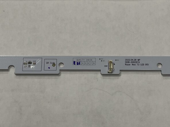
- Disconnect: Using a tool or your fingers, unplug the connector on the RGB board, then set it aside
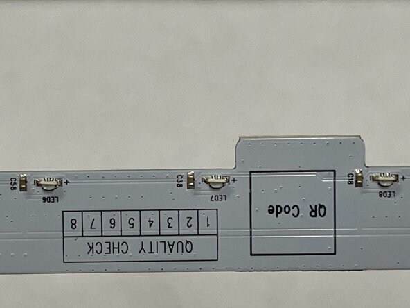
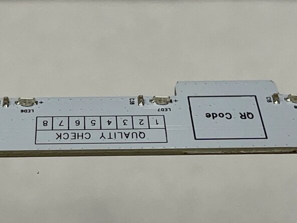
- Close up detail views of the RGB Light Bar PCB. Very simple design.
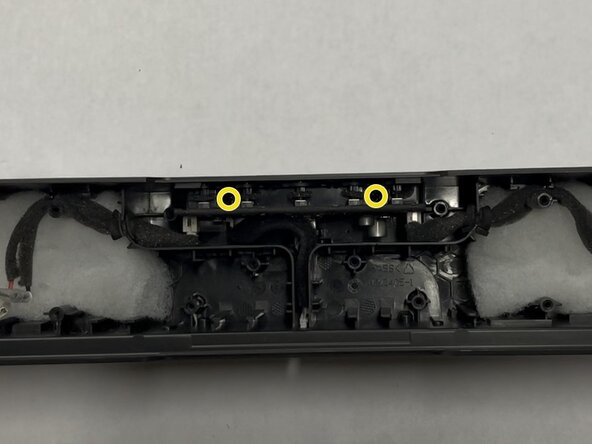
- Use a Philips #2 screwdriver to remove the two 14 mm-long screws holding in the main board.
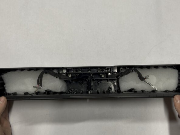
- Pull on the cable for the RGB board and move it to the side to expose the bracket
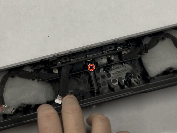
- Use a Philips #2 screwdriver to remove the single 10 mm-long screw holding the USB-C bracket in place
- Note: This screw is the same size as the six screws for the bottom cover.
- Lift and remove plastic bracket covering USB-C Port
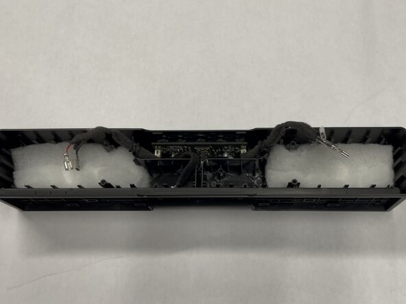
- Slip the speaker cables from their wedged positions and remove the white polyester batting that was behind the two speakers
- Reminder: Leave the foam insulation around the speaker wires, it is there to dampen vibrations and keep the speaker sounding clean.
- Be careful to not damage/bend the USB-C port!
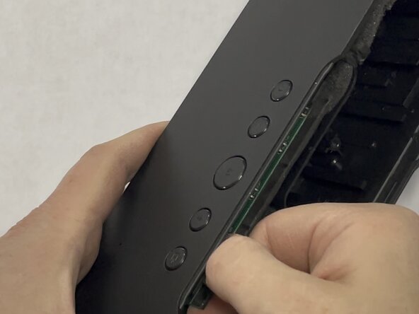
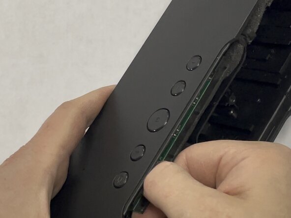
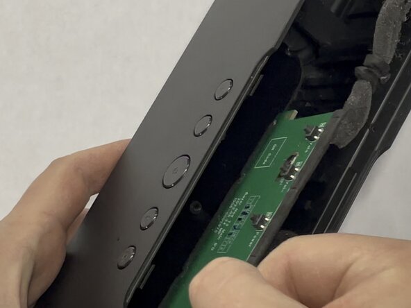
- Firmly grasp the main board with your fingers and gently wiggle back and forth while pulling the board firmly outward.
- Additionally pull at a slight angle downward and away from the buttons to help dislodge the USB-C port.
- The USB-C port is still embedded in the outer frame of the speaker. The intent of this wiggling is to free the USB-C port from the frame of the speaker. This is the only thing still holding the main board in place.
- Continue this wiggling motion until you have gently worked the board out of it's place.
- Note: The main board is pretty wedged in there, so it does take some force to remove. Just be patient, go slow, and it will all be okay.
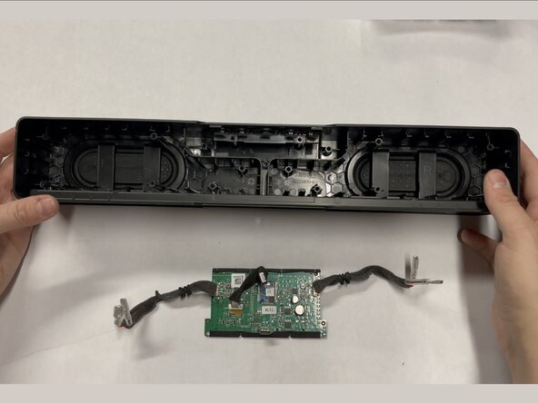
- Remove the main board from the unit and set it aside! 🎉
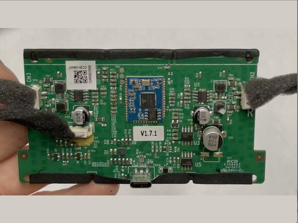
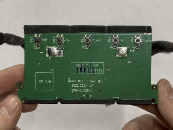
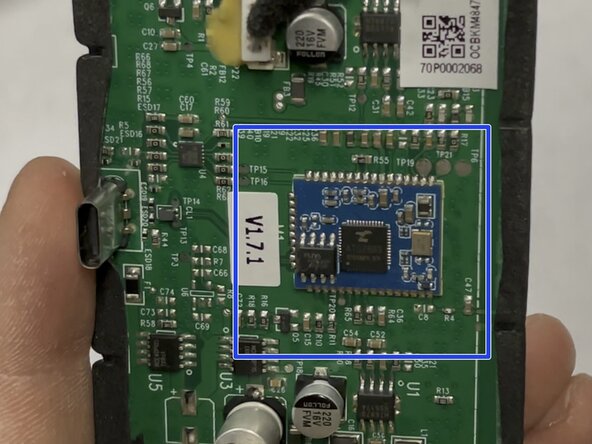
- Close up detail views of the main board.
- Embedded Board: ATS2833 Bluetooth-audio module
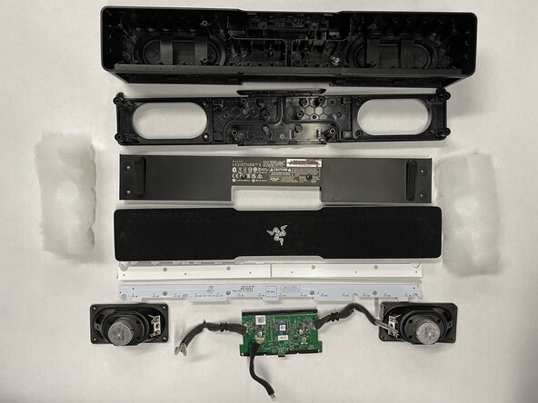
- Follow this guide in reverse to reassemble your device, paying attention to the screw sizing and placement.
- The two rubber "Passive Radiators" on the back of the speaker body are fused to the housing and do not seem removable. If you find a safe way to remove and reattach these, please leave a comment or update this guide.