APC Back-UPS Pro 1000 S Teardown
ID: 194060
Description: ⚠⚡ This device contains high voltage...
Steps:
- Safely shut down and unplug all devices connected to the UPS.
- Hold the power button to power the UPS off.
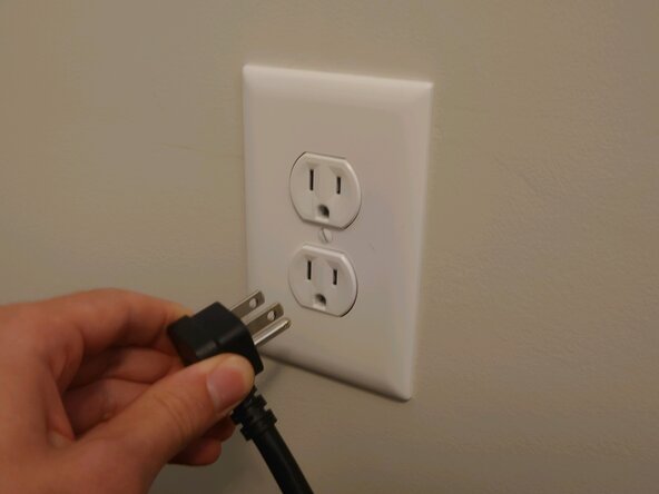
- Unplug the UPS from the wall.
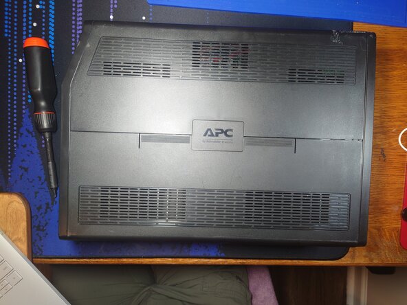
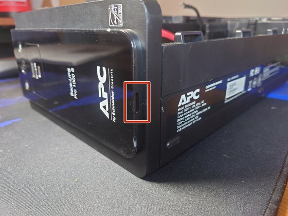
- Lay the UPS on its side. (Validate the orientation using the picture)
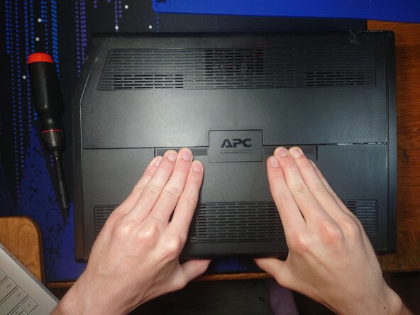
- Push down hard on both sides of the APC logo.
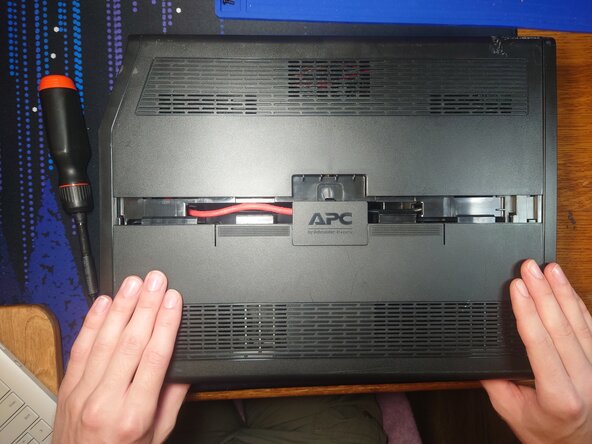
- Pull the slide cover towards you to remove.
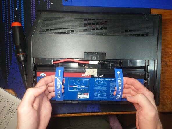
- Pull on the battery pull tabs with the cables still attached. (In the picture the cables are already disconnected)
- There should be enough slack in the cables to set the battery back down at an angle. This will let you access both cables.
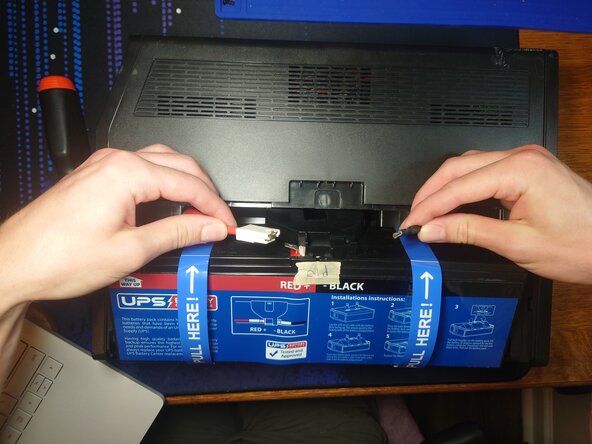
- Unplug both cables. Preferably unplug red first.
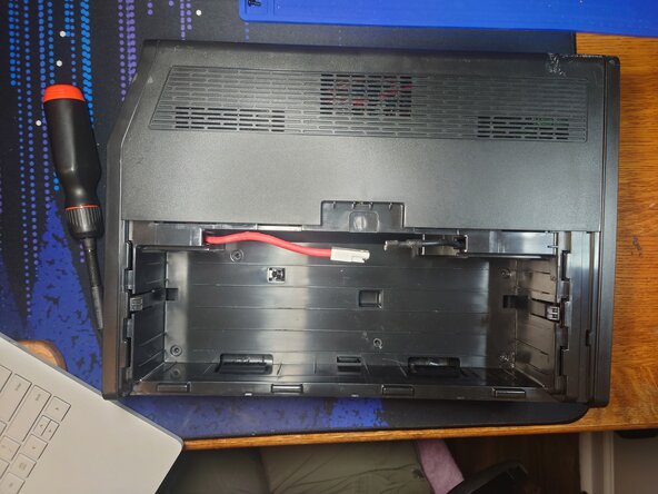
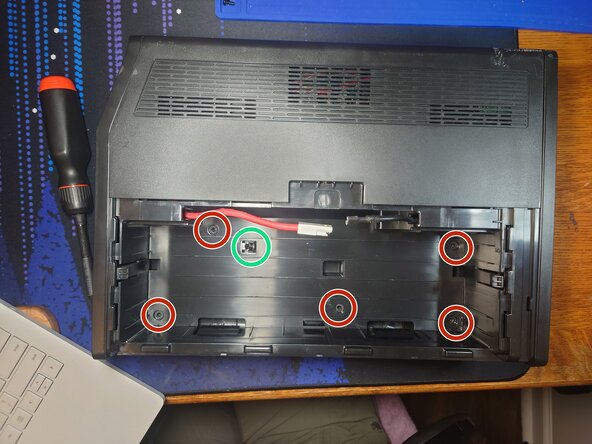
- Remove the 5 phillips head screws in the battery compartment.
- The black component (circled in green) is a temperature sensor. It can be left alone.
- Turn the UPS so the screen faces you.
- Stick a spudger in the cutout (outlined in red) to release the plastic snaps.
- The snaps are firm so take your time and work your way across each edge.
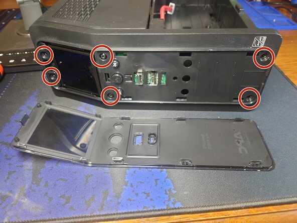
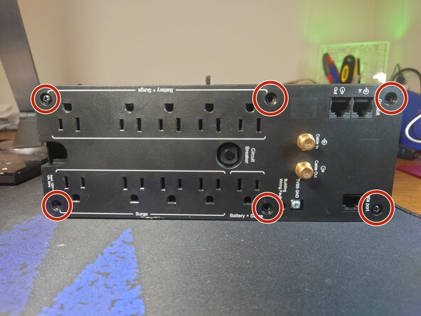
- Remove the 6 phillips head screws (circled in red).
- Pull the face plate toward you to remove. It should take very little effort to remove.
- The buttons are captive and will not fall out.
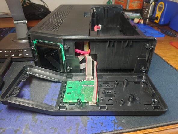
- Remove the two phillips head screws (circled in red).
- These are a different size than the previous screws!
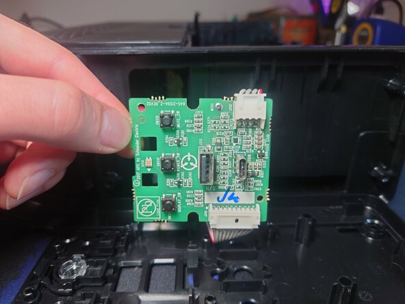
- Lift the low-voltage circuit board to remove it. Note: It pivots at the bottom.
- You may remove the connectors on the circuit board. Refer to this guide for removing connectors: Recognizing & Disconnecting Cable Connectors
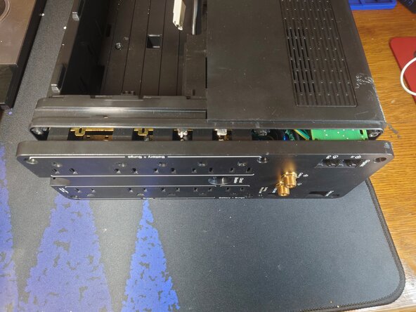
- Turn the UPS with the back facing you.
- Remove the 6 phillips head screws.
- Pull the backplate towards you to remove. It is connected to many wires and could take some effort to get loose. You cannot fully remove it.
- Do not touch any exposed metal since it is connected to the high-voltage circuit board.
- The back plate just needs to be about a centimeter away from the rest of the shell.
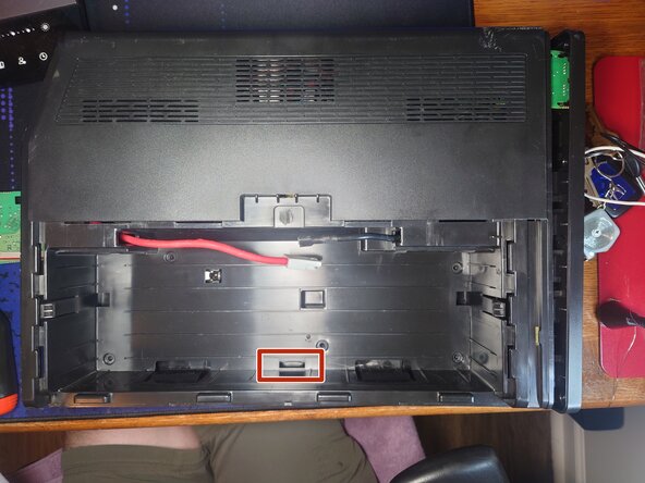
- Turn the UPS with the battery compartment facing you.
- Insert a plastic spudger into the bottom middle hole (outlined in red) to separate the plastic snap.
- There are no high-voltage components in this area.
- Pull up on the plastic shell to release it.
- There are small plastic snaps at the top of the UPS but pulling hard enough should release them without breaking.
- Once the shell is free, remove the cables from the battery compartment. The red wire may take some wiggling but it will fit through the hole.
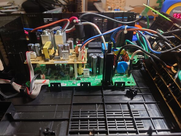
- ⚡ Wear high-voltage PPE for any further disassembly.
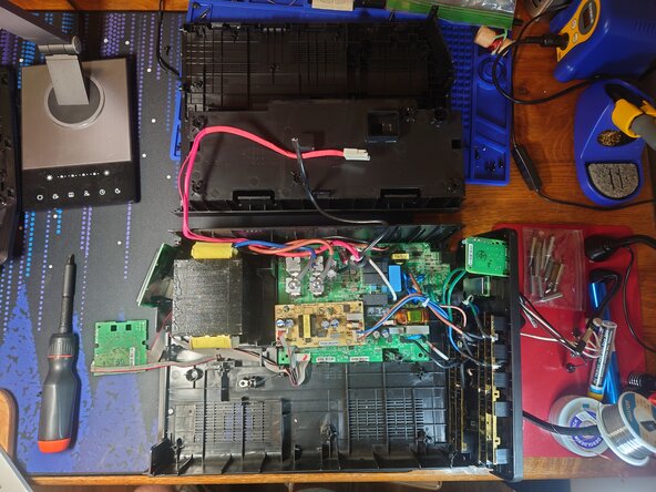
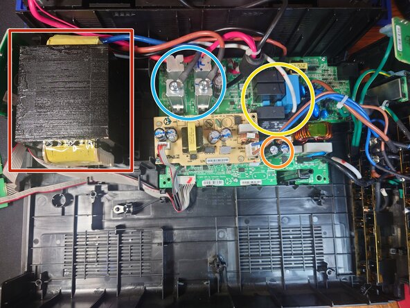
- The transformer (outlined in red) can seriously electrocute you. Do not misuse it.
- Be careful with the 400v capacitors. (circled in orange)
- The metal towers (circled in blue) are heat sinks for mosfets. The mosfet part number is: IRFB7440 IOR P806J JK GO. These can explode under use and trigger an F02 error on the unit.
- The relays (circled in yellow) can break which will also cause an F02 error on the unit.
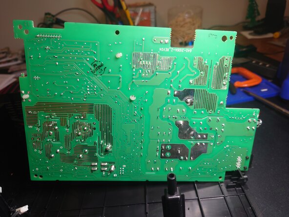
- The bottom of the circuit board cannot be accessed yet. The picture fit better here than the next step though.
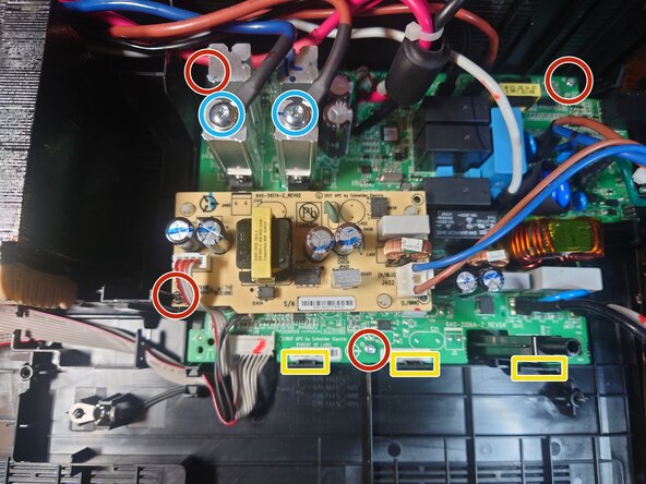
- Unplug all wires from the circuit board. Some are very difficult to remove.
- You cannot remove the thick black and red wire without desoldering.
- Unscrew the 2 Torx T25 screws (circled in blue) on the metal posts to remove the wires.
- Unscrew the 4 phillips head screws (circled in red).
- Release the plastic snaps (outlined in yellow). You may need to pull up on the board to keep the snaps released. The board will pivot at the top.