Pentax PZ-1p Main PCB Removal
ID: 194170
Description:
Steps:
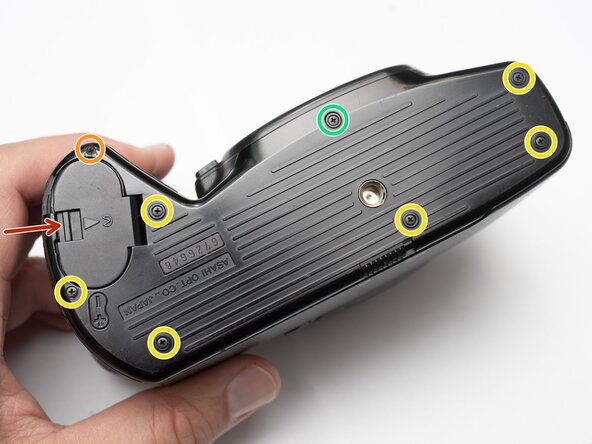
- Unlatch battery compartment door.
- Remove one 1.7 x 4.0 mm screw.
- Remove six 1.7 x 2.5 mm shoulder screws.
- Remove one 1.7 x 2.5 mm long shoulder screw.
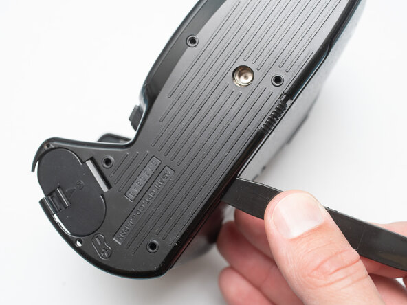
- The bottom cover may be adhered with double sided tape in some locations. Use a spudger to gently work it loose.
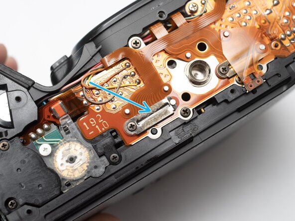
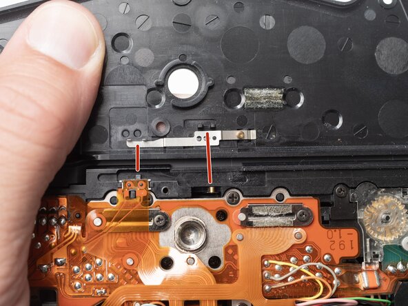
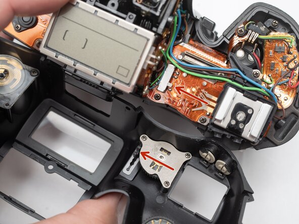
- Check that the physical panorama switch on the bottom cover and the electrical switch mate properly.
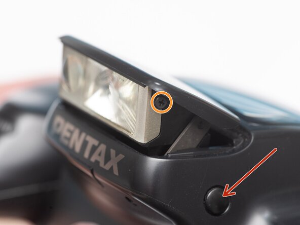
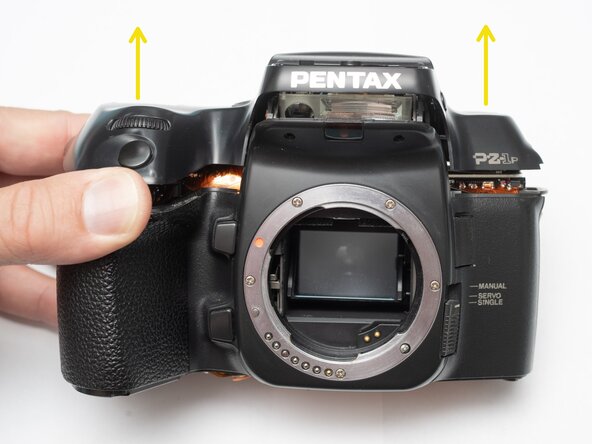
- Push button to pop up the flash.
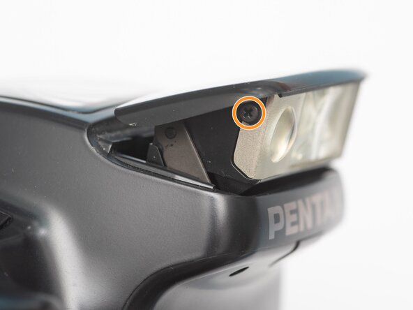
- Remove two 1.7 x 2.5 mm screws.
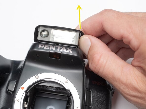
- Detach snaps by lifting the side of the flash cover, bending it up and away from the housing.
- Push flash back down to the stored position.
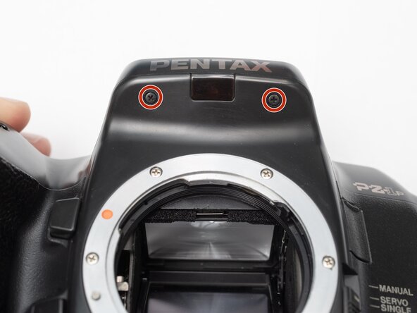
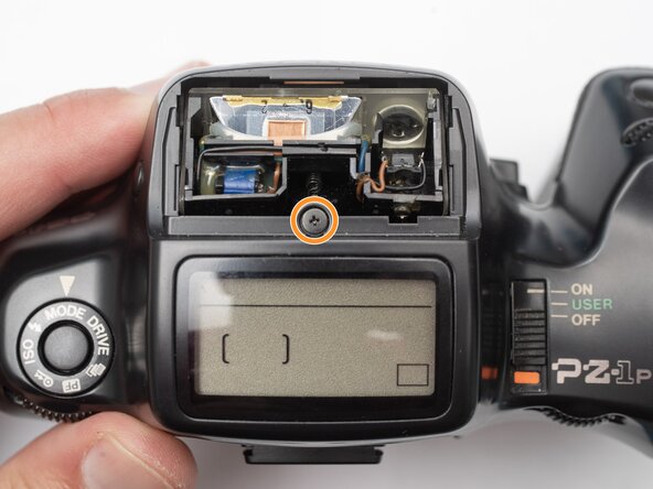
- Remove two 1.7 x 2.5 mm screws underneath the pop-up flash.
- Remove one 1.7 x 2.5 mm panhead screw above the pop-up flash.
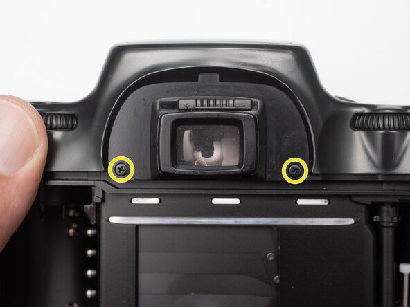
- Remove two 1.7 x 2.5 mm shoulder screws near the eye piece.
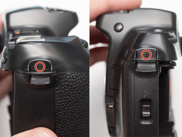
- Remove two 1.7 x 2.5 mm shoulder screws by the strap lugs.
- Remove one 1.7 x 6.0 mm screw inside the battery compartment.
- Lift off the top cover.
- Check that the physical power switch and the electrical power switch are both in the same position before installation.
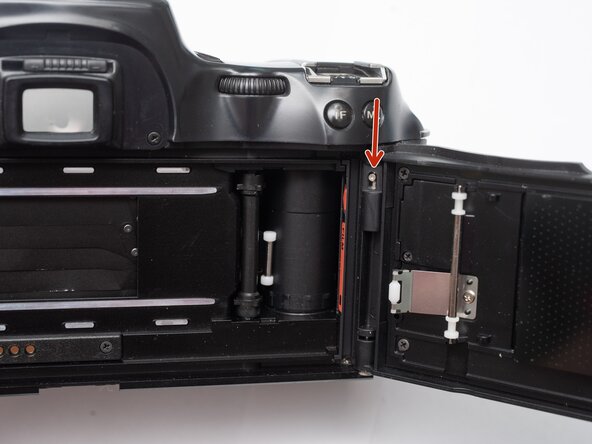
- Push the release latch down to remove the film door.
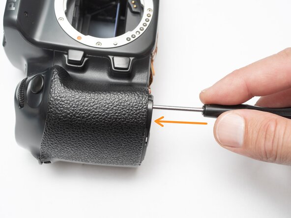
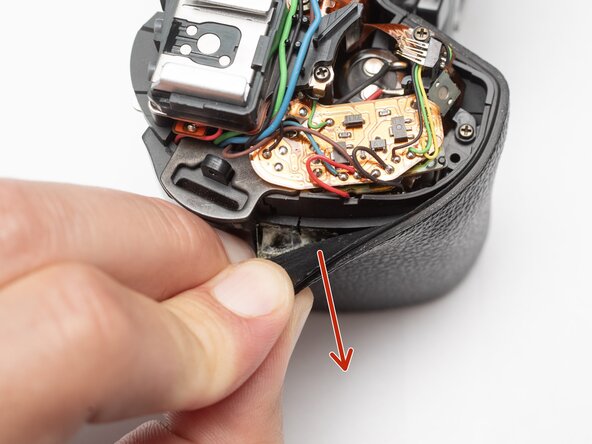
- Peel off rubber covering from grip.
- Remove one 1.7 x 5.0 mm screw.
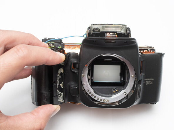
- Lift off the front body panel.
- Connect a 10 kOhm high power resistor across the terminals of the flash capacitor for several seconds.
- Proceeding with the repair without discharging the flash capacitor could result in shock to the repairer or the camera components.
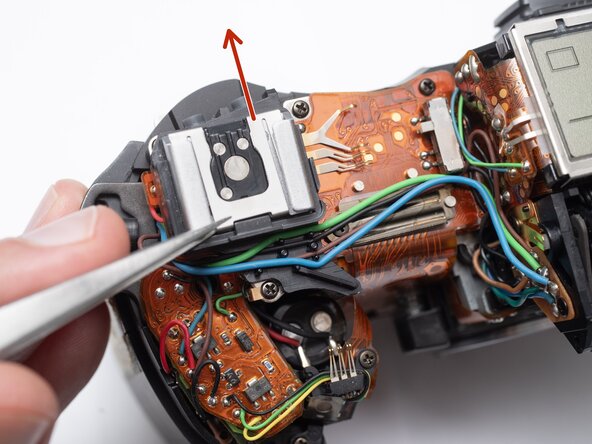
- Remove the hot shoe spring. Lift the front of the spring and slide it towards the back of the camera.
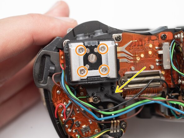
- Remove four M1.7 x 6.5 mm screws from the hot shoe.
- Remove black, brown, green, and blue wires from plastic guides.
- Lift off the hot show mount.
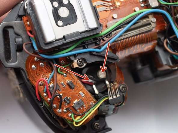
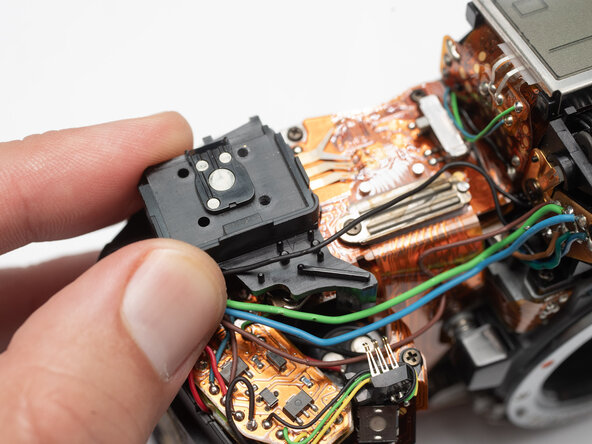
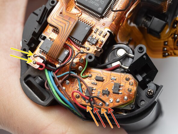
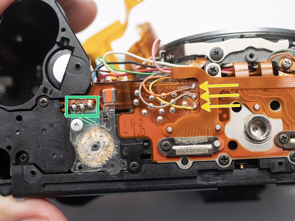
- Unsolder the black, green and yellow wires for the command dial contacts.
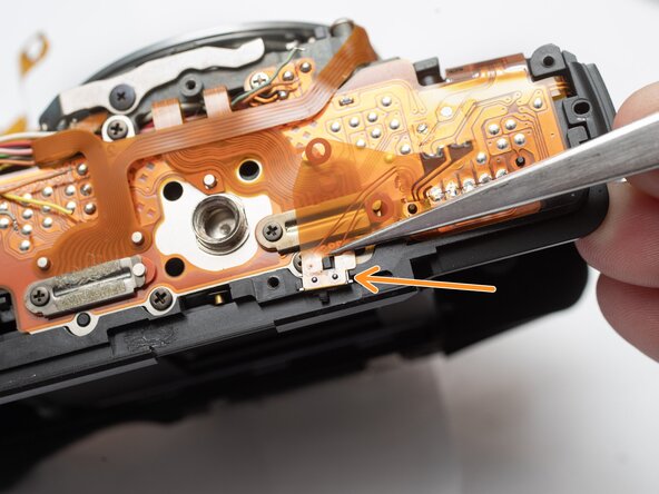
- Remove one 1.7 x 4.5 mm screw.
- Lift off command dial contact.
- Unsolder the blue and green wires.
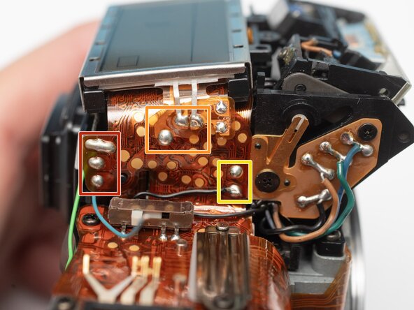
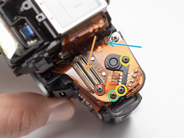
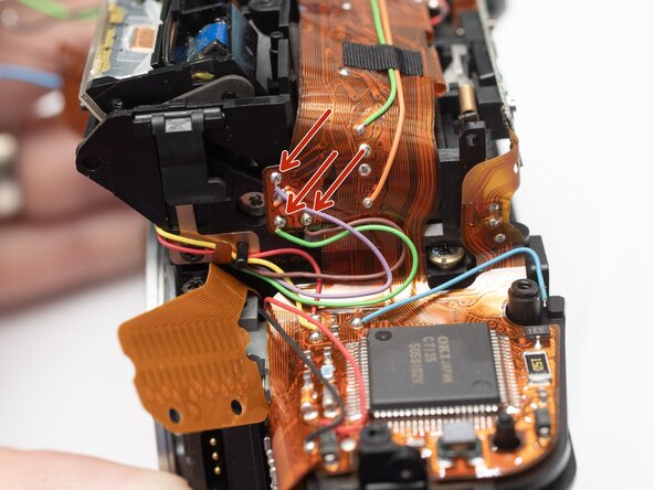
- Unsolder the blue, green, brown and black wires from the flash relay PCB.
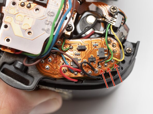
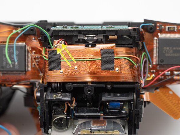
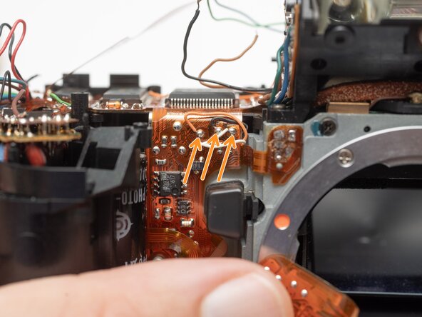
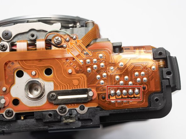
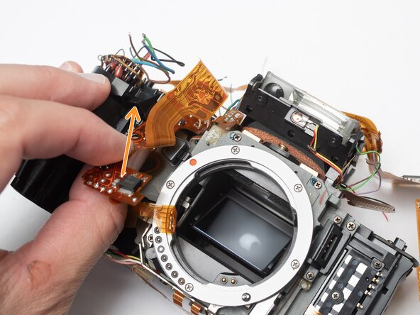
- Unsolder three pads.
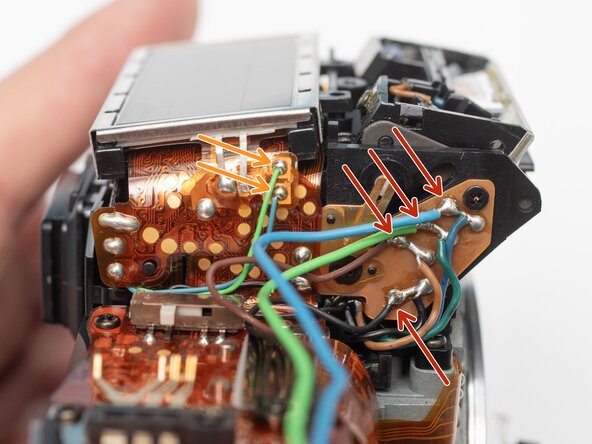
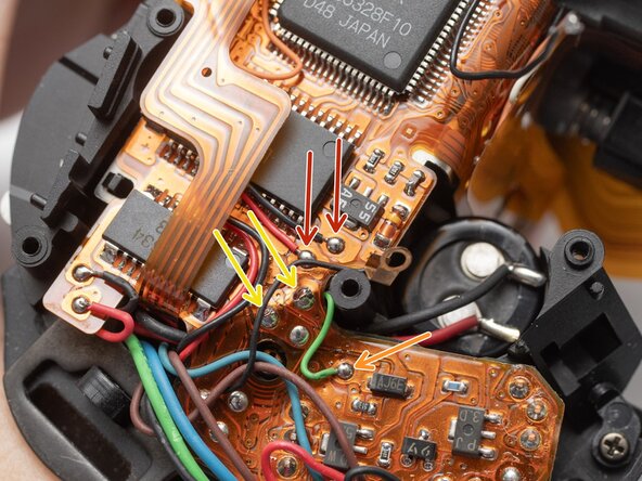
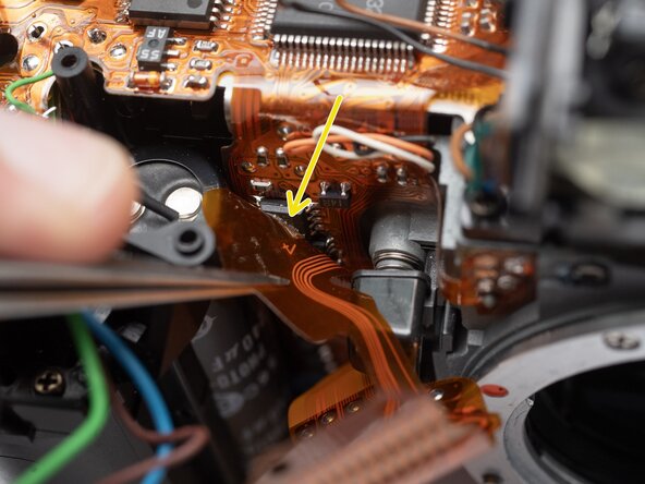
- Unsolder three flex connections.
- Unsolder two through-hole connections.
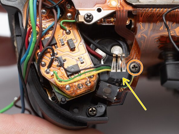
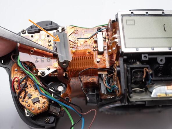
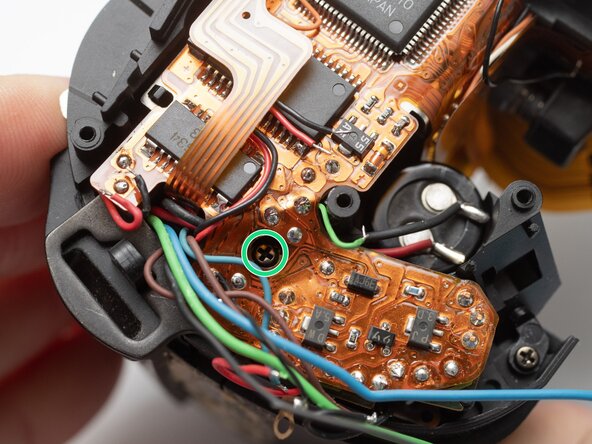
- Remove one M1.7 x 2.5 mm screw.
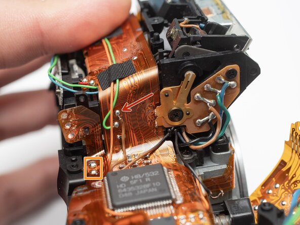
- Remove flex clamp and rubber pad.
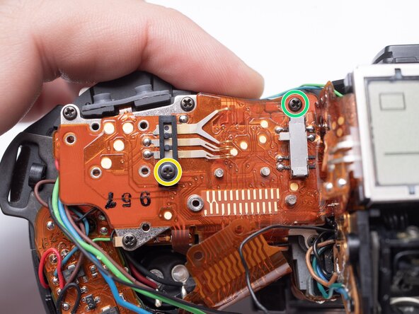
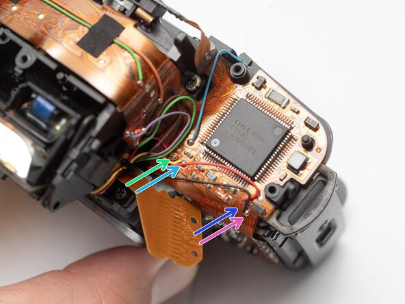
- Remove one M1.7 x 3.5 mm screw.
- Remove one 1.7 x 3.5 mm screw.
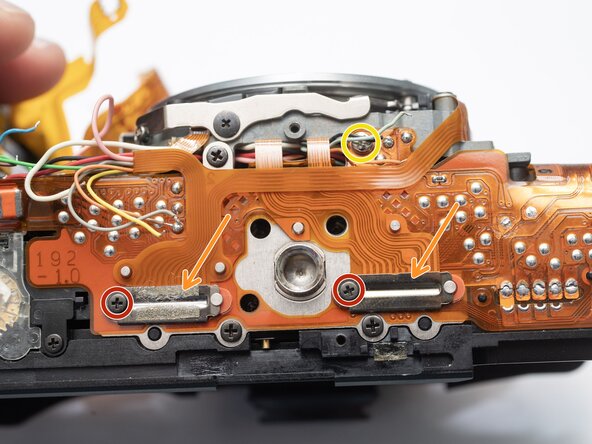
- Remove one M1.7 x 2.5 mm screw.
- Remove flex clamp and rubber pad.
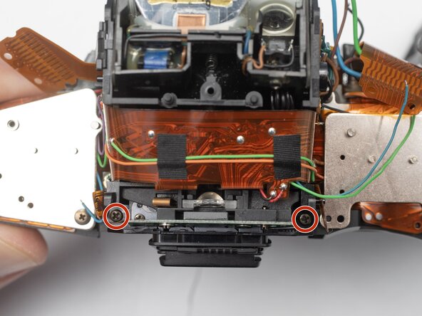
- Remove two M1.7 x 2.5 mm screws.
- Remove one 1.7 x 2.5 mm screw.
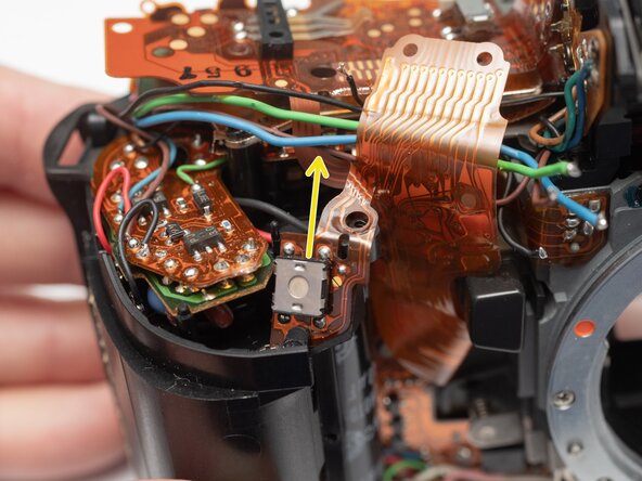
- Unsolder one blue wire.
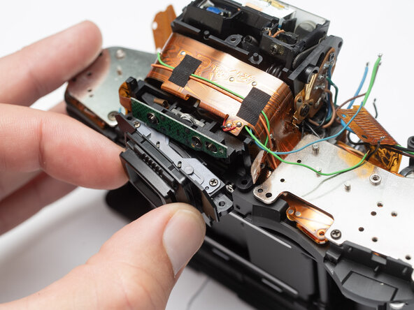
- Remove rubber dome pads for ME an IF buttons.
- Detach button contacts from housing.
- Push shutter release button up to free it from its retention post.
- Detach snaps under the LCD frame.
- Gently lift off LCD flex PCB.
- Remove two 1.7 x 7.0 mm screws.
- Remove the eye piece.
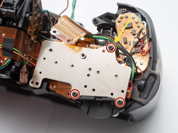
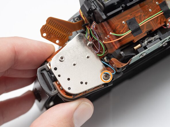
- Remove three 1.7 x 3.5 mm screws.
- Remove one 1.7 x 3.5 mm screw.
- Remove both base plates.
- Installation Notes: Make sure to attach the ground wire at this location when installing the plate.
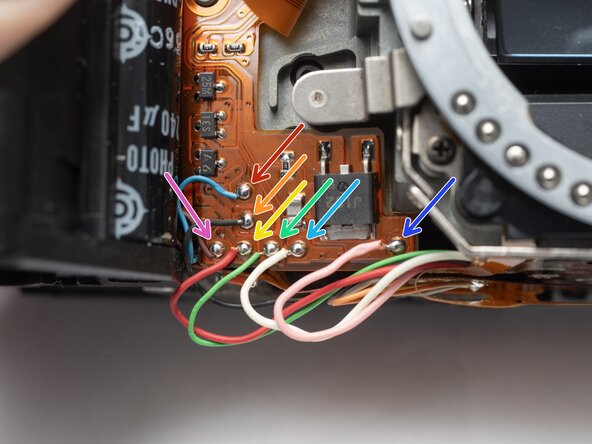
- Unsolder the red and black wires to the battery contacts.
- Unsolder the blue and brown wires.
- Unsolder the red and black wires to the charging motor.
- Unsolder the red and black wires for the film advance motor.
- Unsolder one green wire.
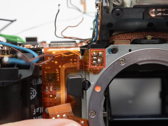
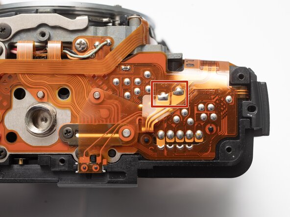
- Unsolder two through-hole connections for the charge block contact.
- Remove one 1.7 x 3.0 mm screw.
- Unsolder one brown wire from the AF spot beam.
- Unsolder two flex connections.
- Unsolder the red and black wires for the buzzer.
- Unsolder the purple, green and brown wires for the aperture resistor.
- Unsolder the red and yellow wires for the self-timer LED.
- Unsolder the red and black wires for the TTL flash meter.
- Unsolder five flex connections for the shutter unit flex cable.
- Unsolder the white, black, and orange wires for aperture control unit.
- Peal the shutter flex cable away from the main PCB. Apply isopropyl alcohol to loosen double-sided tape where necessary.
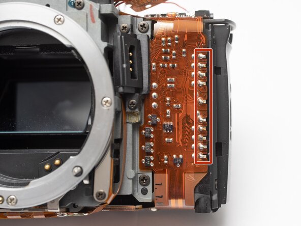
- Unsolder all connections to the DX code reader pins.
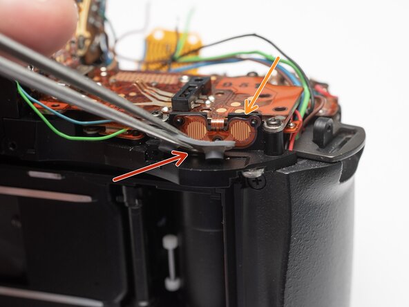
- Unsolder two flex connections for the panorama switch.
- Remove panorama switch.
- Unsolder the blue and brown wires to the aperture control solenoid.
- Unsolder the red and black wires to the AF motor.
- Unsolder the white, pink and green wires to the AF motor unit.
- Unsolder five flex connections to the film door contacts.
- Unsolder the black, orange, and gray wires for the AF motor unit.
- Unsolder the orange, gray and yellow wires for the mirror release solenoid.
- Unsolder three flex connections to the sprocket counter PCB.
- Remove two M1.7 x 2.5 mm screws.
- Remove two flex cable clamps and rubber pads.
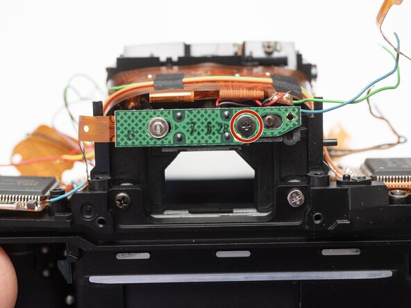
- Remove one M2.0 x 4.0 mm screw.
- Remove one F1.7 x 3.0 mm screw.
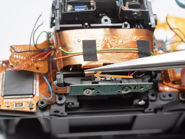
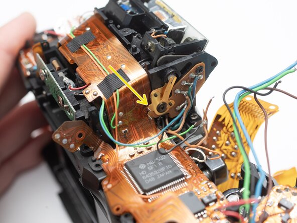
- Use tweezers to pull off one brass clip from the end of the adjustment post.
- Installation Notes: Consult page 32 of the Z1 service manual to adjust the precise position of the metering cell. This should be done before the LCD flex PCB is installed.
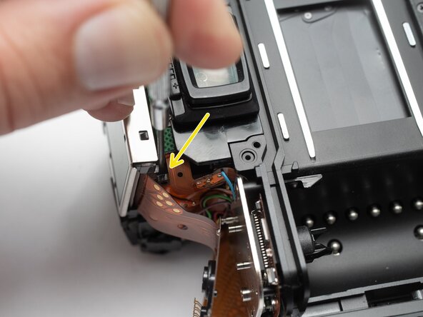
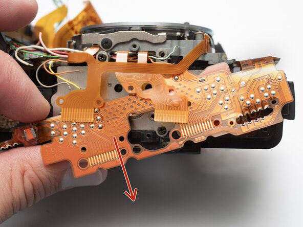
- Begin by freeing the PCB from the bottom of the camera.
- Work up and around the top.
- Carefully work free the section between the grip and the lens mount.
- Watch for areas where the flex may catch.
- Slowly lift the entire PCB away from the camera looking for snags and wires that may still be connected.