How to Replace the Thermal Pad in your Framework Desktop
ID: 194202
Description: Follow this guide to replace the thermal pad...
Steps:
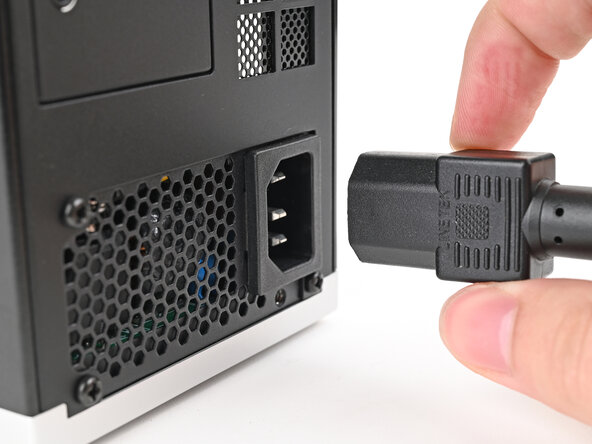
- Before you begin repairs, shut down your desktop from the operating system and unplug it.
- Wait one minute before continuing to allow your Desktop to fully power down.
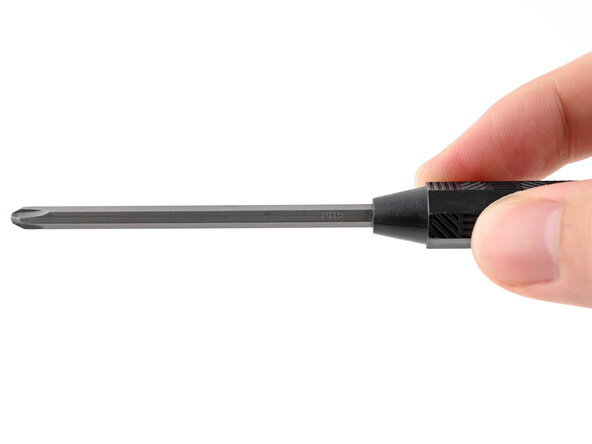
- Make sure your Framework Desktop Screwdriver has the Phillips #2 bit (labeled as PH2) facing outwards. If it's not, pull the bit out and flip it.
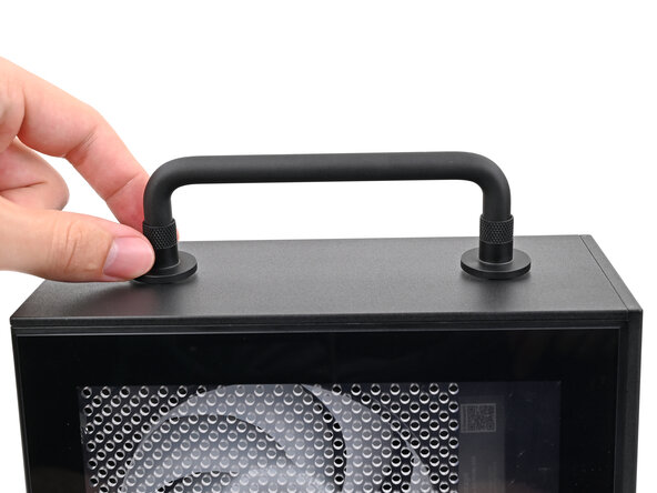
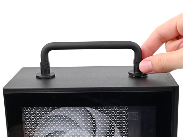
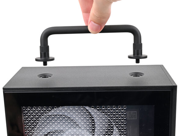
- If you installed the Handle on your Desktop, follow this step. Otherwise, skip it.
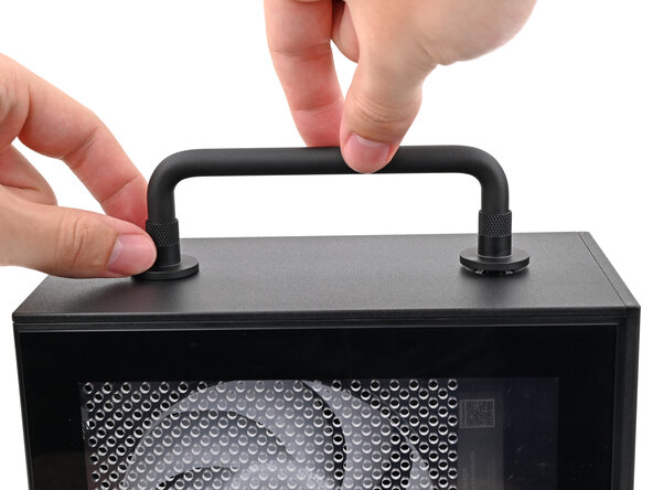
- Rotate the Handle's screw threads counterclockwise on both sides until it comes free.
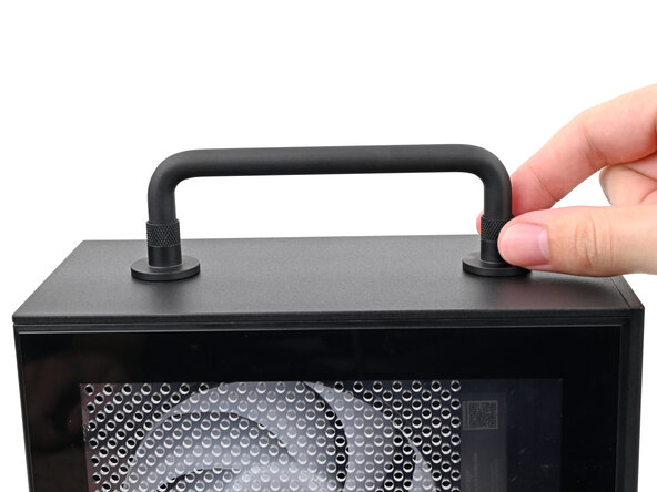
- Remove the Handle.
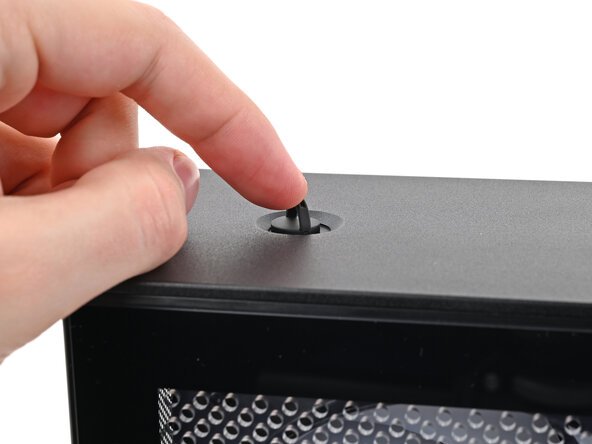
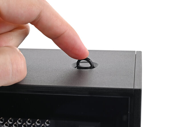
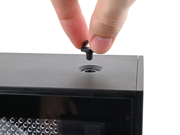
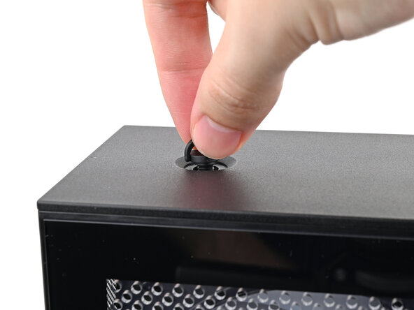
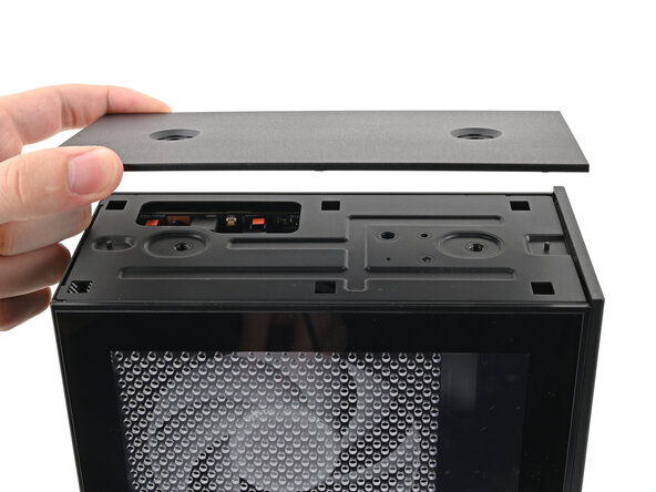
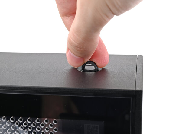
- Use your finger to lift up the two D-rings on the Top Panel screws.
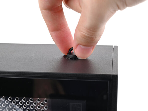
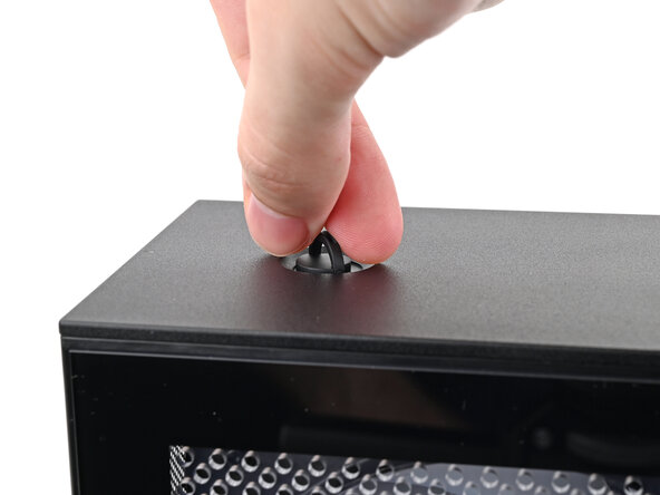
- Use your fingers to twist the screw counter-clockwise and loosen it.
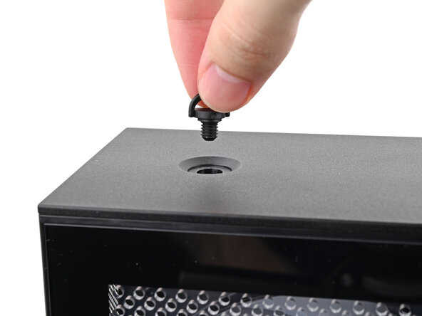
- Remove the Top Panel screw.
- Repeat the same procedure for the other Top Panel screw.
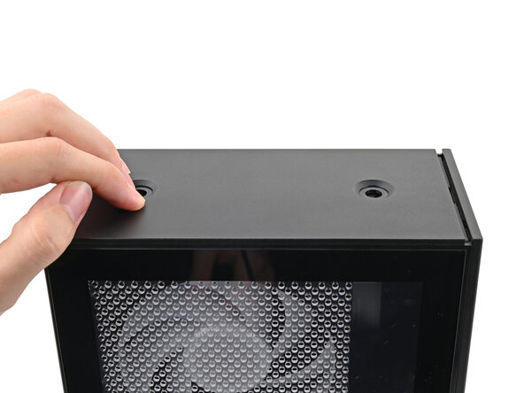
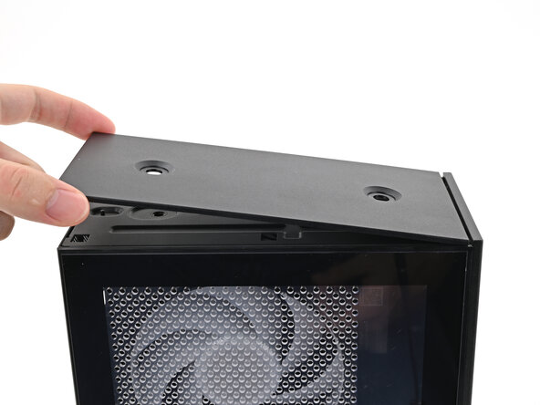
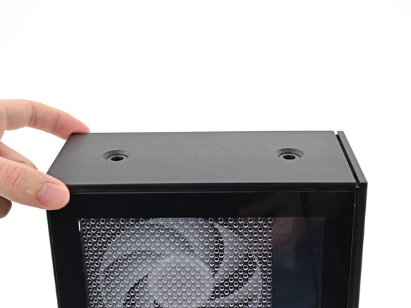
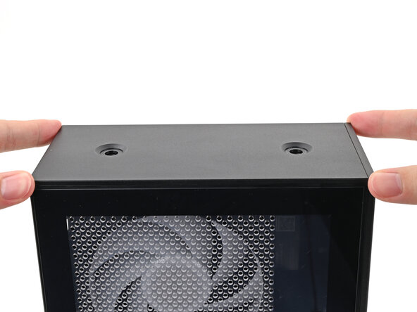
- Slide the Top Panel towards the rear of the computer to release the clips securing it to the chassis.
- If you're having a hard time gripping the Top Panel, use the screw holes to get a better handhold.
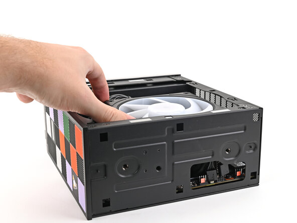
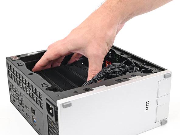
- Lift the Top Panel off the chassis and remove it.
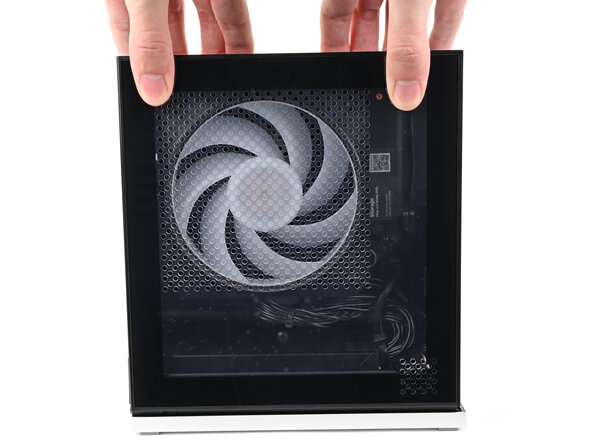
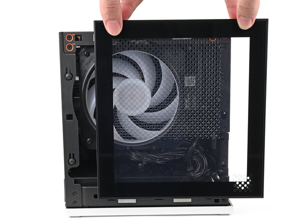
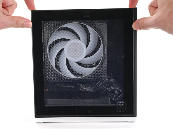
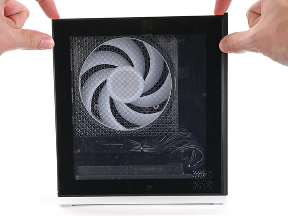
- Use your fingers to grip the top of the Left Panel and slide it upward to release its clips.
- Remove the Left Panel.
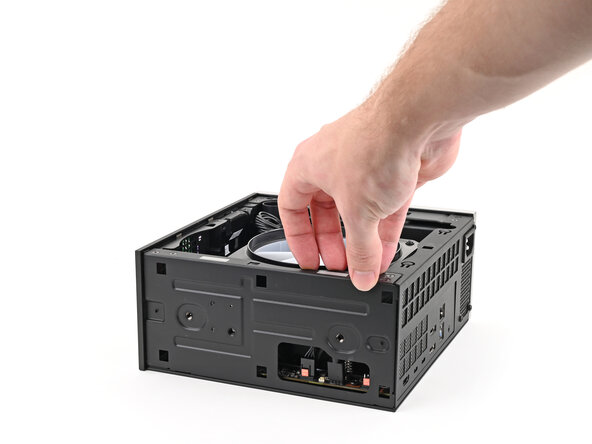
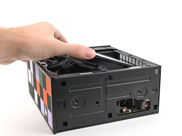
- Lay down the Desktop on its side so the fan is facing upward.
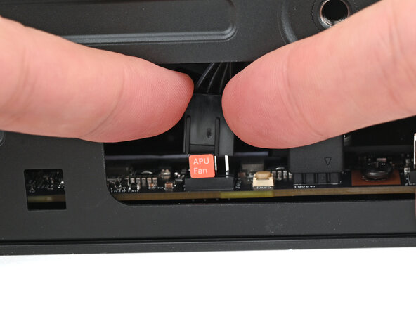
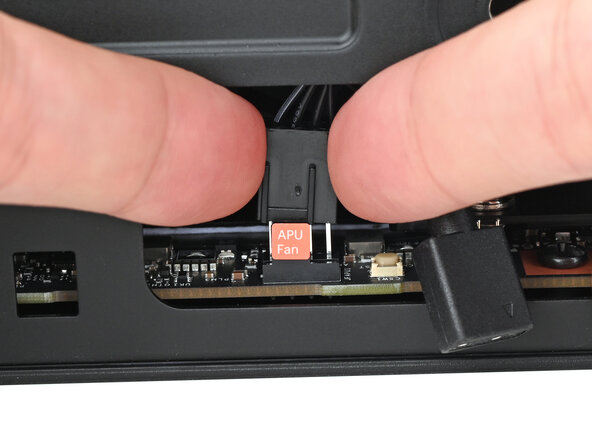
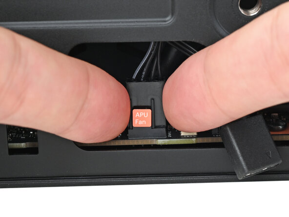
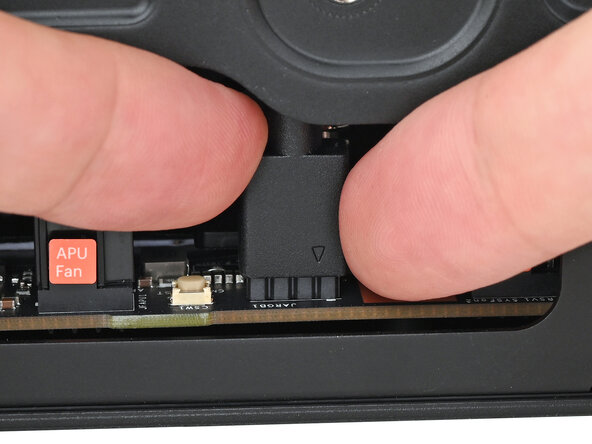
- Use your fingers to lift the APU fan cable connector off its four‑pronged socket on the Mainboard.
- If you aren't using an RGB fan, then skip this step.
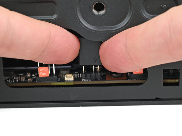
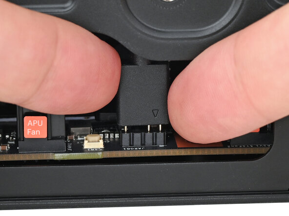
- Use your fingers to lift the fan RGB cable connector off its three‑pronged socket on the Mainboard.
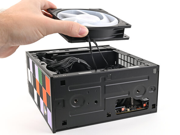
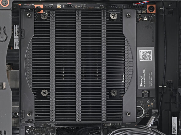
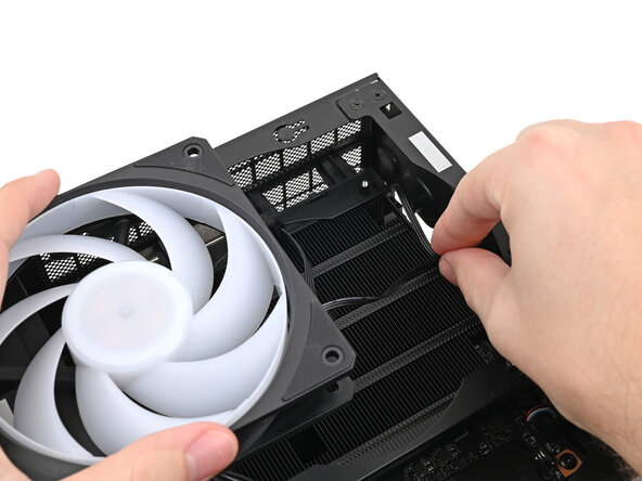
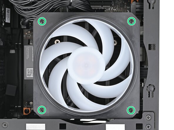
- Use your Framework Desktop Screwdriver to remove the four 27.3 mm‑long Phillips screws securing the CPU fan and fan duct.
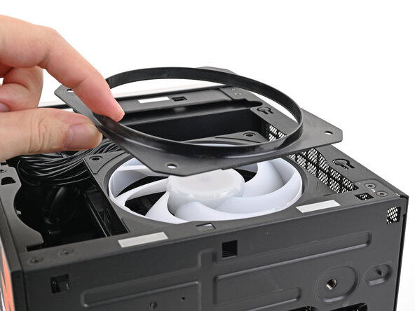
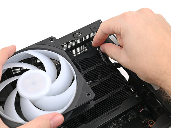
- Lift the fan duct off the fan and remove it.
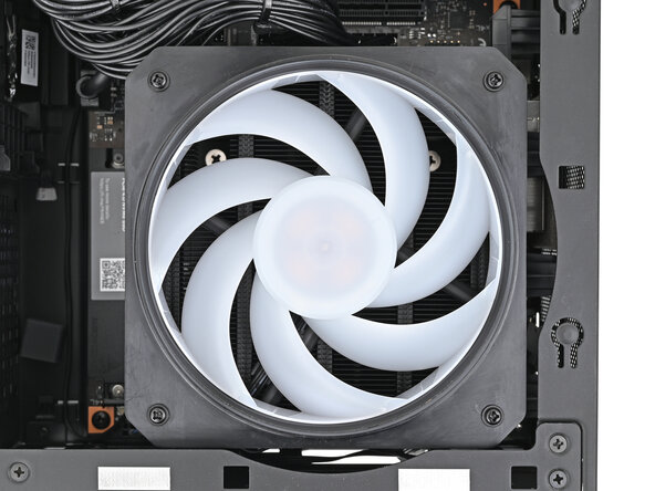
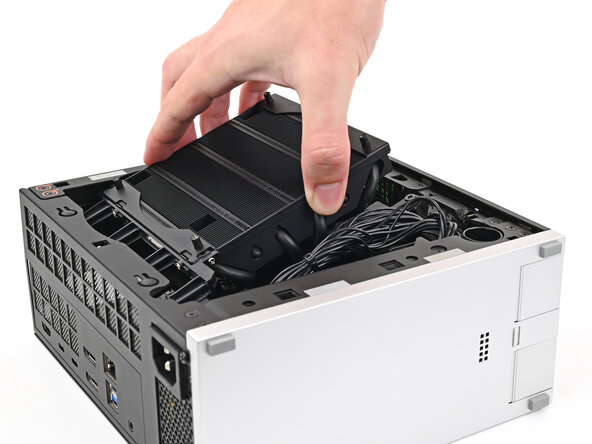
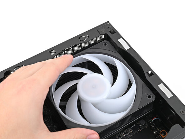
- Lift the fan out of the chassis, making sure the cables thread through the side of the heatsink.
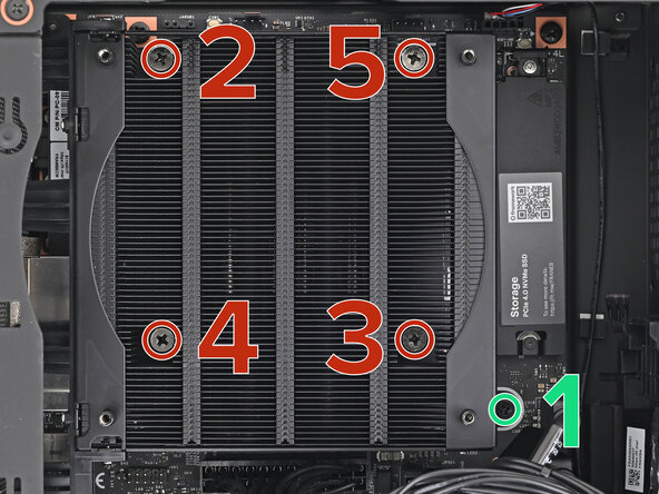
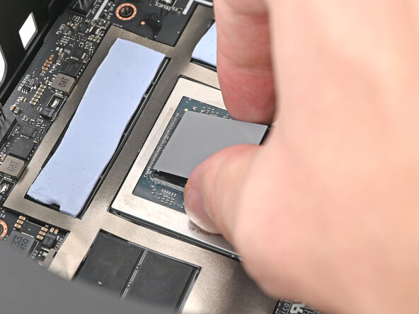
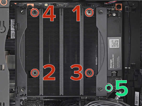
- Use your Framework Desktop Screwdriver to loosen the final captive Phillips screw jutting out under the Primary Storage.
- Use your Framework Desktop Screwdriver to loosen the four captive Phillips screws securing the heatsink in an "X" pattern starting with the top left screw.
- Only loosen the screws a few turns at a time to avoid applying uneven pressure to the APU.
- In order: top left→ bottom right→ bottom left→ top right
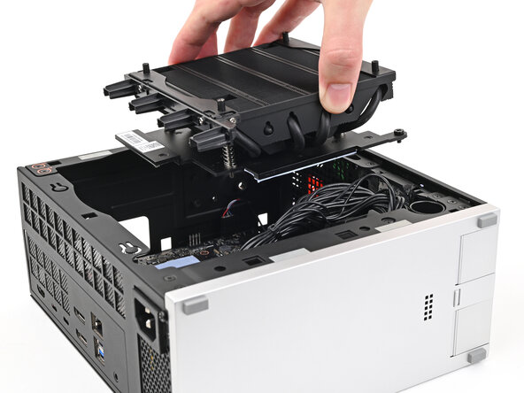
- Lift the heatsink and tilt it up towards the front of the Desktop to navigate it out of the chassis.
- Remove the heatsink and rest it on your work area upside down to avoid damaging the thermal pads.
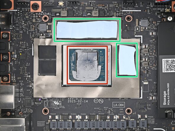
- There are two types of thermal pads in the Desktop:
- One thin, grey pad covering the back of the APU
- Four thicker, blue pads covering the memory and power management
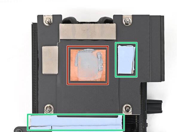
- Upon removing the heatsink, the thicker pads will stick to either the bottom of the heatsink or to the Mainboard. Keep them in place and use your fingers to reposition them over their slots if they got folded or partially moved.
- Follow the remaining steps to remove the thin thermal pad and replace it.
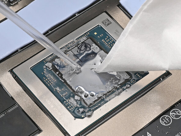
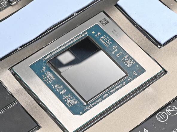
- Apply a few drops of isopropyl alcohol (>90%) to the APU and use a coffee filter or a lint-free cloth to wipe away any residue.
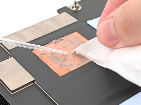
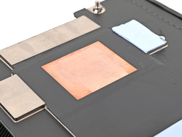
- Repeat the cleaning procedure on the heatsink.
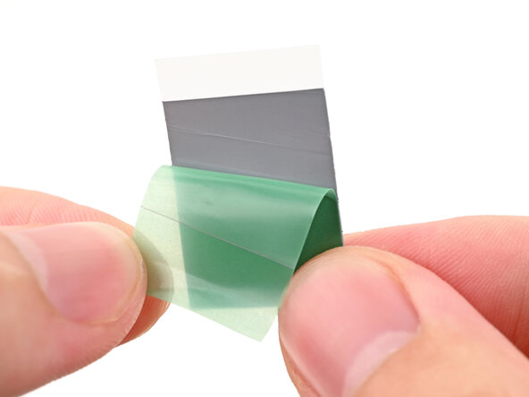
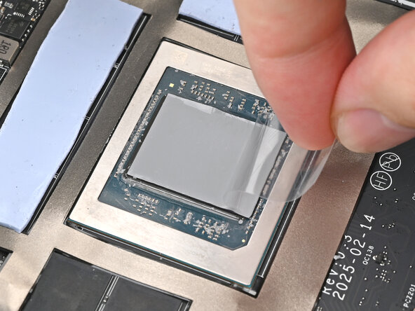
- Remove the green liner from the replacement thermal pad to expose one side of it.
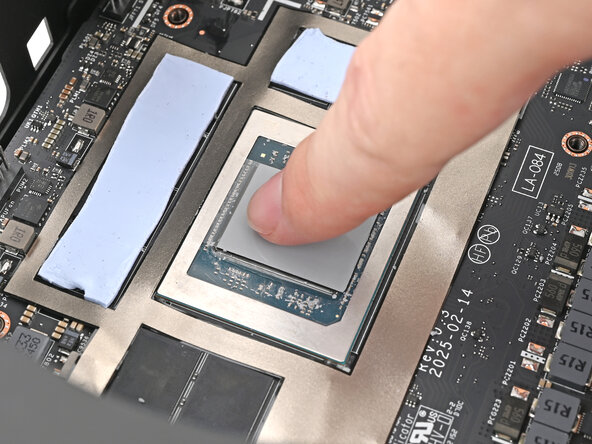
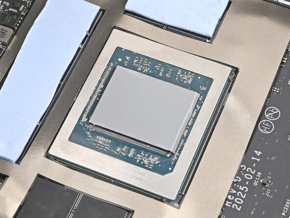
- Place the exposed side of the thermal pad over the APU and press it into place.
- If you have trouble handling your thermal pad, you can store it in your fridge for a few minutes to make it more rigid.
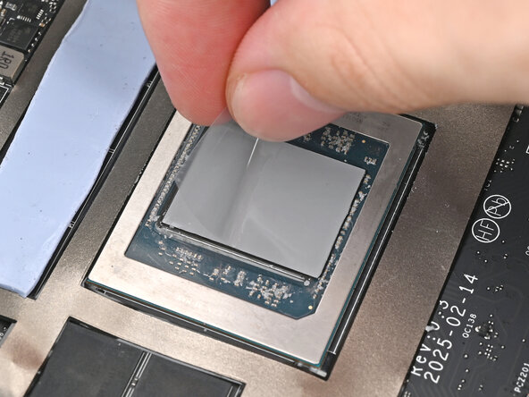
- Remove the clear liner from the thermal pad to expose its top side.
- Tilt the heatsink down towards the rear of the Desktop and place it into its slot on the Mainboard.
- Use your Framework Desktop Screwdriver to tighten the four captive Phillips screws securing the heatsink in an "X" pattern starting with the top right screw.
- Only tighten the screws a few turns at a time to evenly compress the APU and thermal pads.
- In order: top right → bottom left → bottom right → top left
- Use your Framework Desktop Screwdriver to tighten the captive Phillips screw jutting out under the Primary Storage.
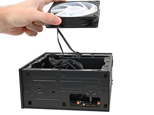
- Orient the fan so its label is facing downward and the cable(s) is pointing towards the top of the computer.
- If your fan has an arrow indicating airflow direction, make sure it's pointed towards the heatsink.
- If you're using a different fan, orient it such that the fan is blowing towards the heatsink, not away.
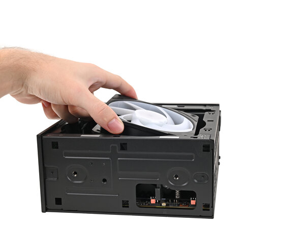
- Lay the fan on top of the heatsink, making sure the cables are routed so they poke out of the hole on the top of the computer.
- If the cables aren't routed properly, lift the fan up slightly and use your fingers to reposition the cables over the side of the heatsink.
- If you're installing an RGB fan, make sure the "male" end of the RGB cable is covered and set aside in the corner of the chassis.
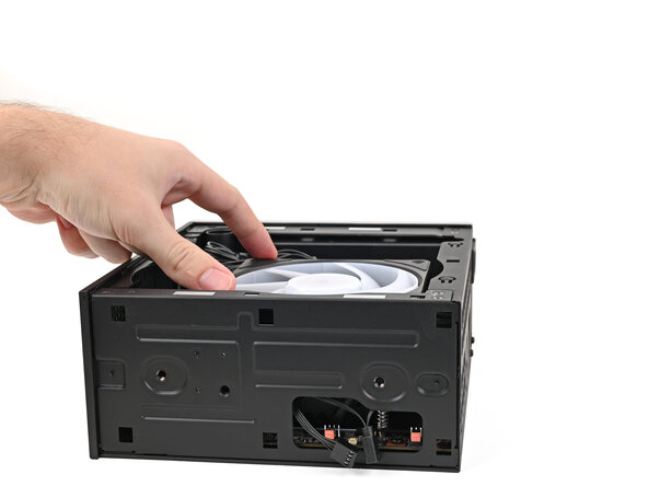
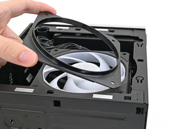
- Lay the fan duct on top of the fan with the lip facing upward.
- Align the screw holes on the fan duct with the ones on the fan.
- Use your Framework Desktop Screwdriver to install the four 27.3 mm‑long screws securing the fan and fan duct.
- Orient the main fan cable so its two vertical lines are facing you.
- Slide the main fan cable over the four-pronged connector labeled "APU Fan," making sure the orange label slots between the vertical lines.
- If you aren't using an RGB fan, then skip this step.
- Orient the RGB cable so the arrow is on the right side of the connector.
- Use your fingers to slide the RGB cable over the three pronged connector located to the right of the "APU Fan" connector.
- Slide the Left Panel onto the left edge of the chassis and press it flat to ensure its clips are slotted into place.
- There should be a small gap between the bottom of the Left Panel and the silver base.
- Push the Left Panel towards the base of the computer to close the gap and engage the clips.
- Orient the Top Panel so its arrow is pointing towards the rear of the computer.
- While holding the Top Panel at a slight downward angle, slide it across the top of the chassis (from rear to front) until you feel its clips catch.
- There should be a small gap between the Top Panel and the front of the Desktop.
- Lay the Top Panel flat on the chassis to align the remaining clips.
- While securing the computer with one hand, use the other hand to slide the Top Panel towards the front of the computer to close the gap and engage the clips.
- If you're installing the Handle on your Desktop, follow this step. Otherwise, skip it.
- Place the Handle over the Top Panel screw holes.
- While holding the Handle in place, twist the screw threads on both sides clockwise until they're snug on the Top Panel.
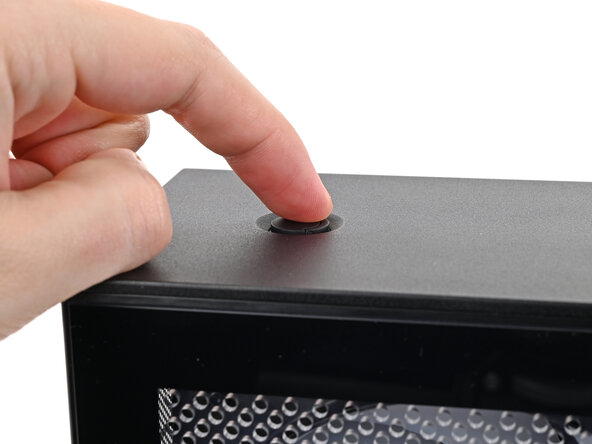
- Insert the top panel screw into its hole and twist clockwise until it feels snug.
- Repeat the same procedure for the other top panel screw.
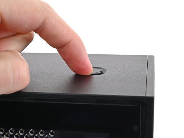
- Use your finger to close the two D-rings on the top panel screws.