Framework Laptop 16 Memory Replacement
ID: 195135
Description: Follow this guide to remove and replace the...
Steps:
- Unplug all cables and fully shut down your laptop.
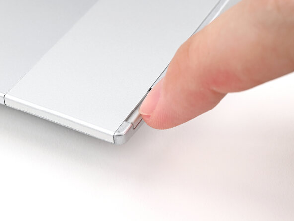
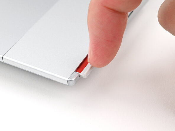
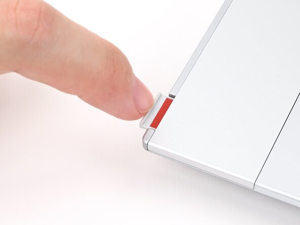
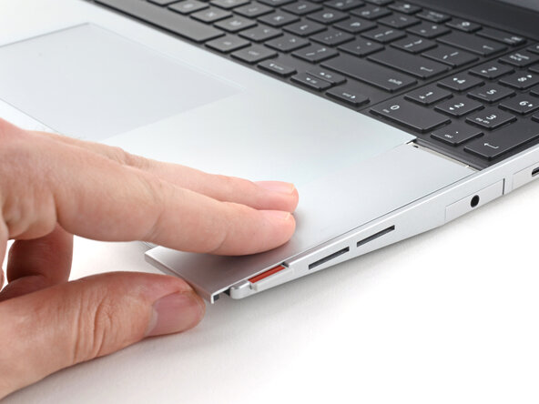
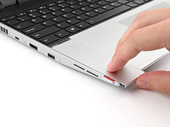
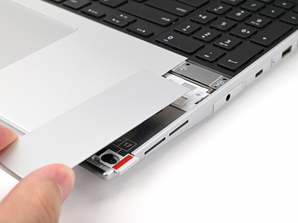
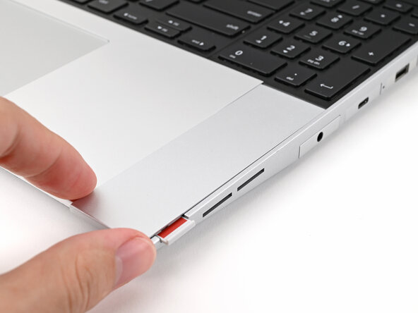
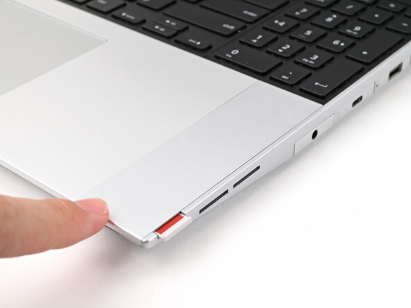
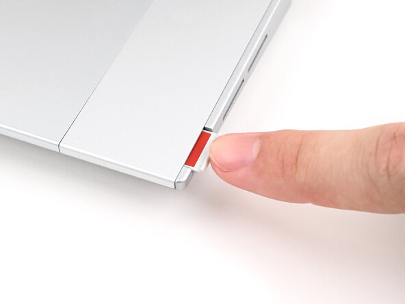
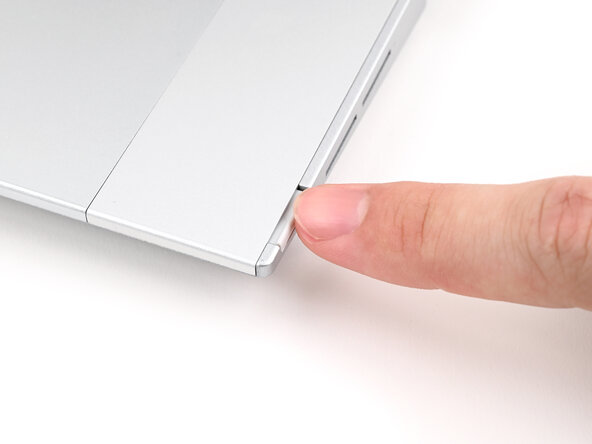
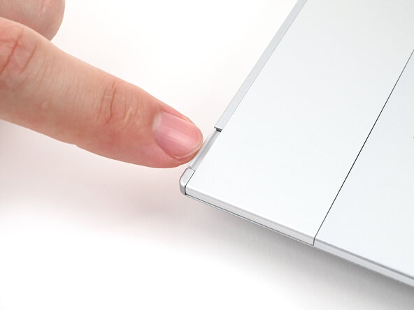
- Use your fingernail to pull out the two Input Module latches and unlock them.
- The latch will show red if it's unlocked.
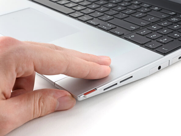
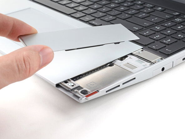
- Use your fingers to slide the Touchpad Spacer toward the bottom edge of the laptop and unclip it.
- If you're having trouble, check if the corresponding Input Module latch is properly unlocked.
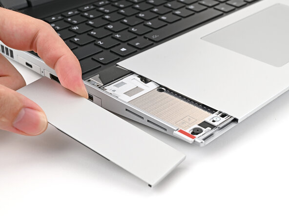
- Lift the Touchpad Spacer off the laptop and remove it.
- Repeat the same procedure for the other touchpad spacer.
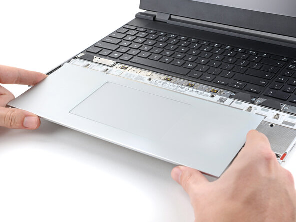
- Use your fingers to slide the Touchpad Module toward the bottom edge of the laptop and disconnect it.
- If you're having trouble, check if the Input Module latches are properly unlocked.
- Lift the Touchpad Module and remove it.
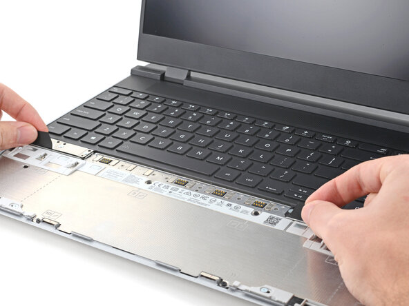
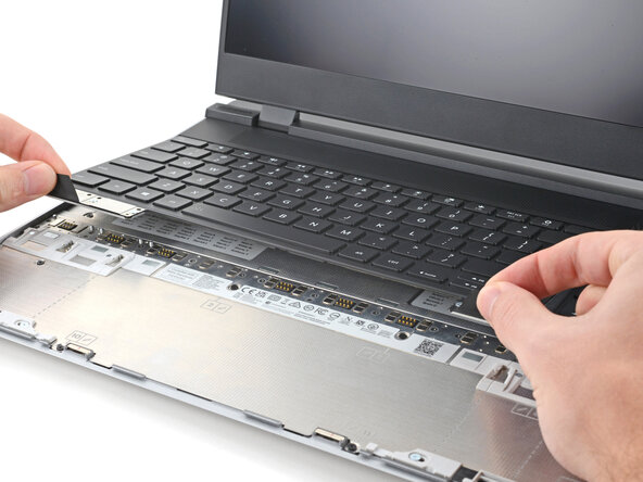
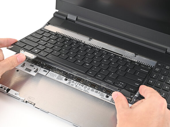
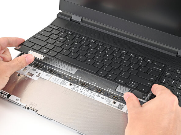
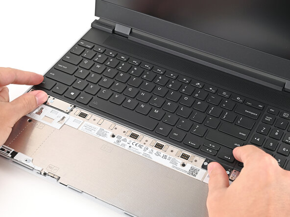
- The keyboard is held in place with strong magnets. Apply gradually increasing force to avoid having the keyboard violently eject.
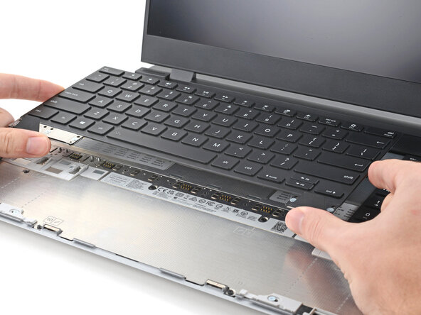
- Grip the two pull tabs along the bottom of the keyboard and lift until its magnets release.
- Remove the keyboard.
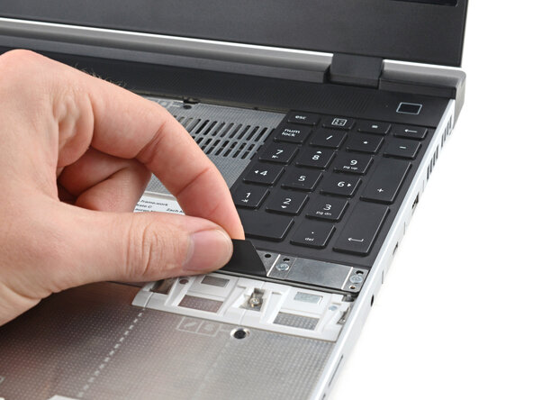
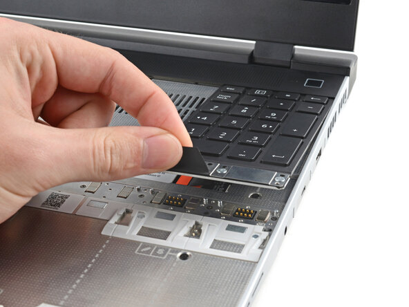
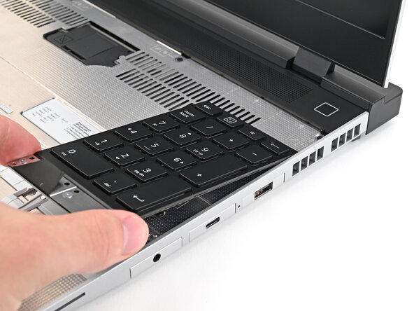
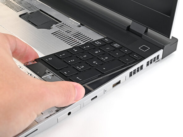
- Your Input Module(s) might be different, but the procedure to remove them is the same.
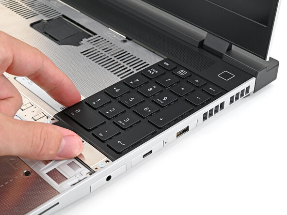
- Grip the pull tab at the bottom of the Input Module and lift until its magnets release.
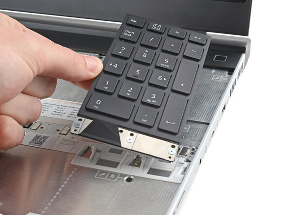
- Remove the Input Module.
- Repeat for any remaining Input Modules.
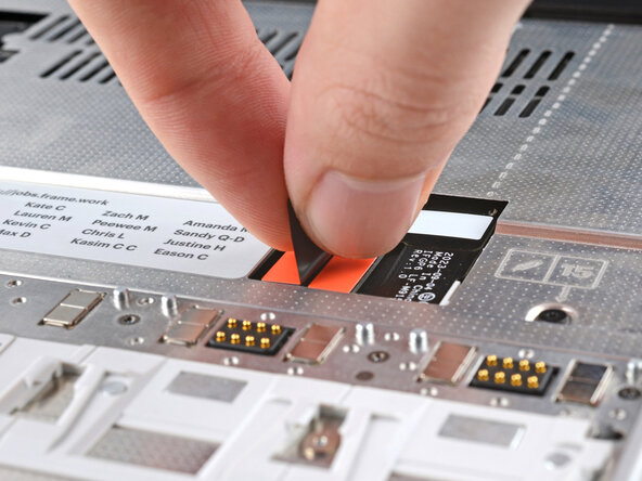
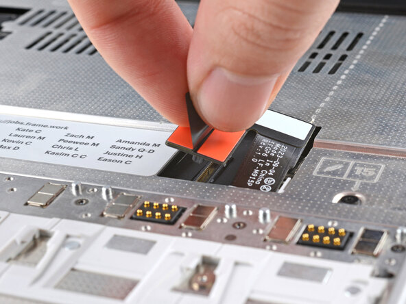
- Grip the black pull tab on the Mid Plate cable press connector.
- Lift up to disconnect the Mid Plate cable.
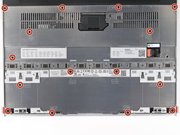
- The Mid Plate screws are ordered from 2–17 (number 1 is the press connector). You don't have to follow the order, but you can use it to help keep track of the screws you've loosened.
- Use your Framework Screwdriver to loosen the 16 captive T5 Torx screws securing the Mid Plate.
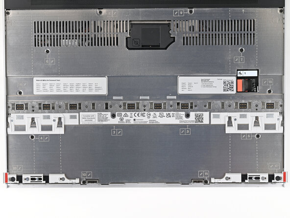
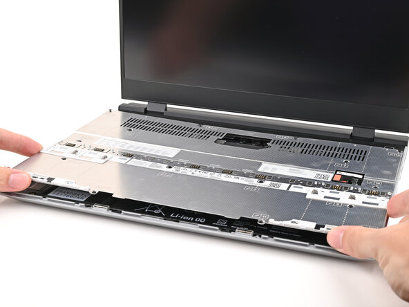
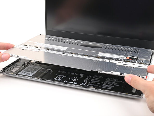
- Use your fingers to lift the Mid Plate off the laptop and remove it.
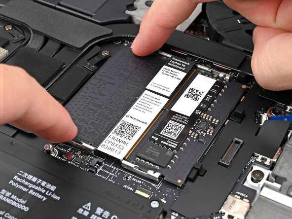
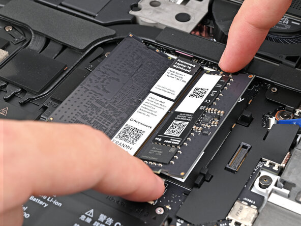
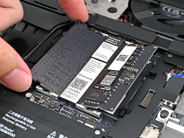
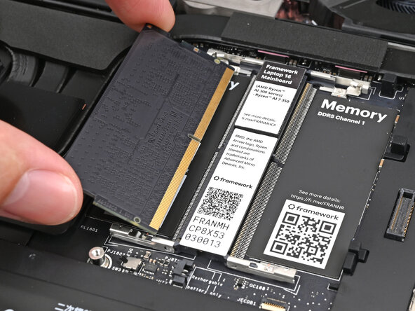
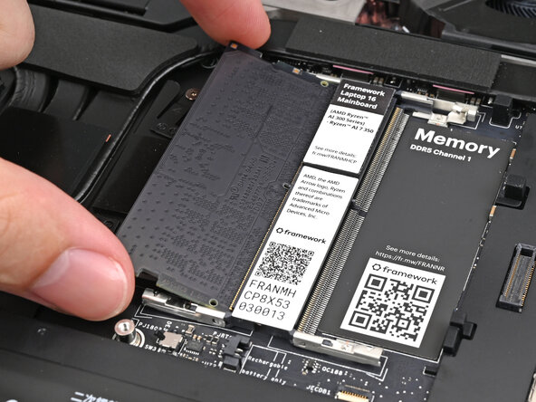
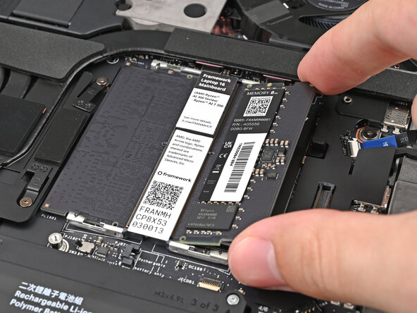
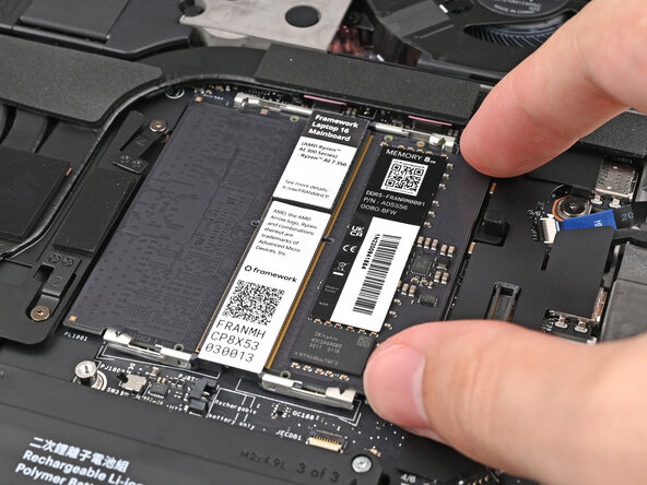
- Push the two metal arms on each side of the module outward until they disengage and the stick pops up at a shallow angle.
- Repeat for the other module.
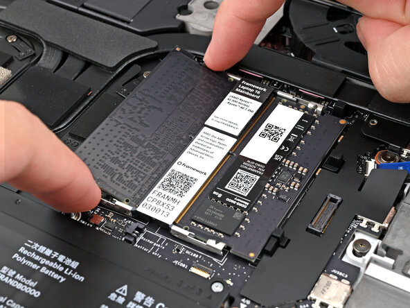
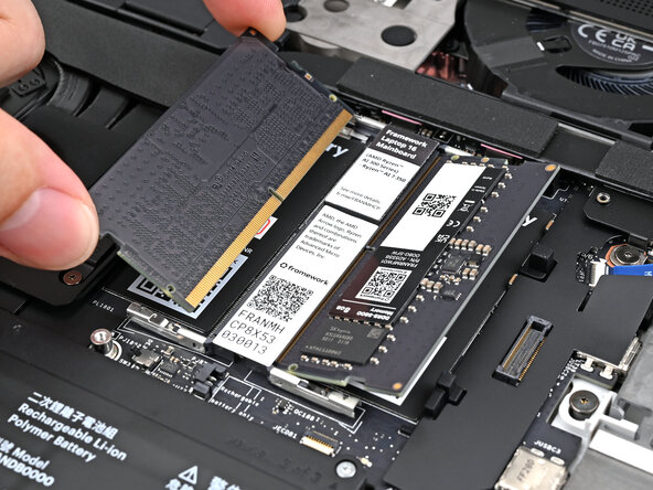
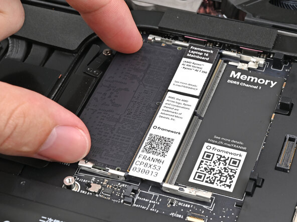
- Slide the memory module out of its socket and remove it.
- Repeat for the other module.
- Congratulations on completing disassembly! The remaining steps will show how to reassemble your Framework Laptop.
- Hold the memory module by its edges. Don't touch the gold contacts with your fingers. If you do, wipe the contacts with a clean, lint-free cloth to remove any finger oils.
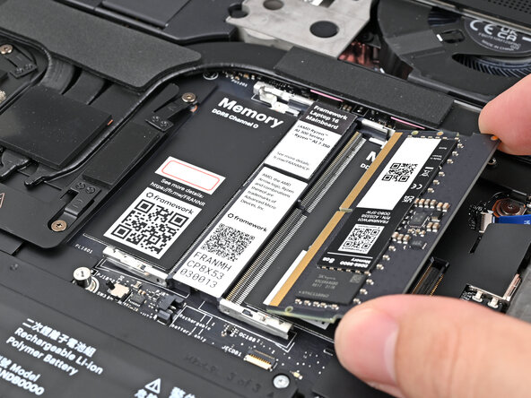
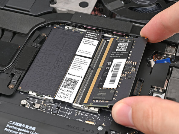
- Orient the module with its label facing down and align the gold contacts with the left socket labeled DDR5 Channel 0.
- Insert the contact edge into the socket at a shallow angle. The gold contacts should mostly be covered by the socket.
- Press the edges of the module down until the side clips lock it in place.
- Repeat the previous step for the other socket labeled DDR5 Channel 1, except orient the module so its label is facing upward.
- Place the Mid Plate on the laptop, making sure it sits evenly on its alignment pegs.
- Use your Framework Screwdriver to tighten the 16 captive T5 Torx screws in order (starting with 2) to secure the Mid Plate evenly.
- Align the Mid Plate cable press connector over its socket and press down to connect it.
- Your Input Module(s) might be different, but the procedure to remove them is the same.
- Align the top edge of the Input Module with the top edge of the laptop.
- Lay the Input Module on the laptop and let the magnets pull the keyboard into place
- Make sure the Input Module is seated properly on its alignment pegs and sits flush with the edges of the laptop.
- Repeat for any remaining Input Modules.
- Align the top edge of the keyboard with the top edge of the laptop.
- Lay the keyboard on the laptop and let the magnets pull the keyboard into place
- Make sure the keyboard is seated properly on its alignment pegs and sits flush with the edges of the laptop.
- Place the Touchpad Module flat on its cutout so its clips are properly aligned.
- Press the Touchpad Module down and slide it into place so it lines up evenly with the bottom edge of the laptop.
- Place the Touchpad Spacer over its spot on the laptop with the bottom edge overhanging slightly.
- Slide the Touchpad Spacer towards the top of the laptop to secure it.
- Repeat the same procedure for the other Touchpad Spacer.
- Push the Input Module latches back into place to lock them.