Dell XPS 15 9570 CMOS Battery Replacement
ID: 199332
Description: This is a guide for replacing the CMOS battery...
Steps:
- Make sure your device is powered off and unplugged before starting
- Flip the device over so the base cover of the computer is facing upwards.
- Using a Torx T5 screwdriver, remove the ten 3 mm screws on the back.
- Flip open the system badge and with a Phillips #00 screwdriver, remove the two 8.5 mm screws.
- Lift the back cover off of the device.
- Using the Phillips #00 screwdriver, remove the four 4 mm screws holding the battery in place.
- Use the iFixit opening tool to disconnect the battery connector from the motherboard.
- With your hands, pick up and remove the battery from the system.
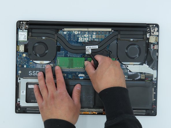
- Use the Phillips #00 to remove the three (without graphics card) or four (with graphics card) 3 mm screws that connect the heat sink to the system board.
- Lift the heat sink from the device. The thermal paste may have dried and make this handling more complicated, be careful.
- Use the Phillips #00 screwdriver to remove the two 4 mm screws securing the grey display cable bracket.
- Using the Phillips #00 screwdriver, remove the 4 mm screw at the back right corner of the fan.
- Disconnect the fan cable on the left of the fan and on the right side from the RAM, using the opening tool.
- Lift the right fan off of the device.
- Repeat steps 8-11 to remove the left fan from the system board.
- The left fan is fixed with two 4 mm screws. Make sure you have removed them if the fan does not come off easily.
- Use your fingers to pinch down the metal tabs holding the RAM in place. Do this for each tab.
- Use your hands to carefully lift the RAM up and away from the tabs to safely take it out.
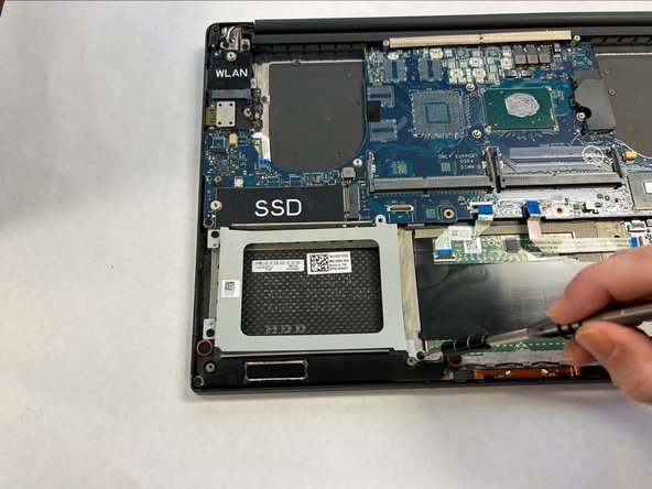
- Use the Phillips #00 screwdriver to remove the 5.5 mm screw next to the SSD.
- Using your hands, hold the SSD and slightly pull to the left.
- Using a Phillips #00 screwdriver, loosen the captive screw holding the wireless card bracket in place.
- Lift the wireless card bracket off of the wireless card.
- Using a spudger, disconnect the coaxial antenna cables from the Wi-Fi card by popping them gently off.
- Carefully remove the wireless card.
- Disconnect the two motherboard cables located on the bottom of the motherboard using the opening tool.
- Using a Phillips #0 screwdriver, remove the four 4mm screws securing the hard drive cover.
- Disconnect the two motherboard cables located on the right of the motherboard using the opening tool.
- Using a Phillips #0 screwdriver, unscrew the 4 remaining 4mm screws holding the motherboard in place.
- Remove the motherboard.