Motorola Edge Plus 2022 I/O Board
ID: 199731
Description: The I/O Board serves two primary functions: it...
Steps:
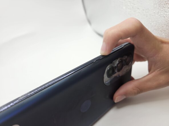
- Press and hold the power button for 7 seconds.
- You will know the phone is fully powered off when the Motorola logo appears on the screen.
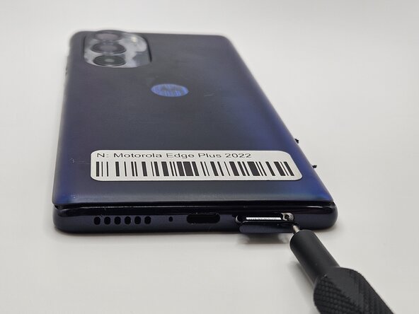
- Insert a paperclip or SIM card ejector into the small hole located at the bottom of phone.
- Gently push to release and remove the SIM card.
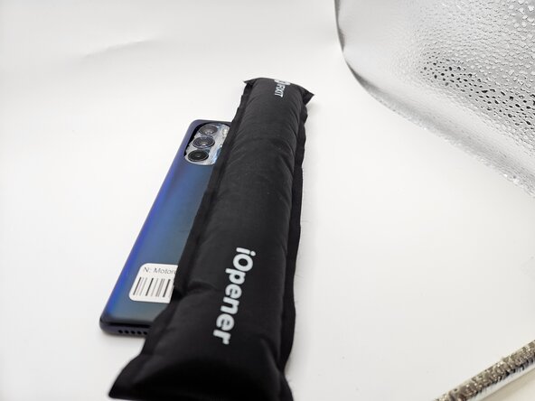
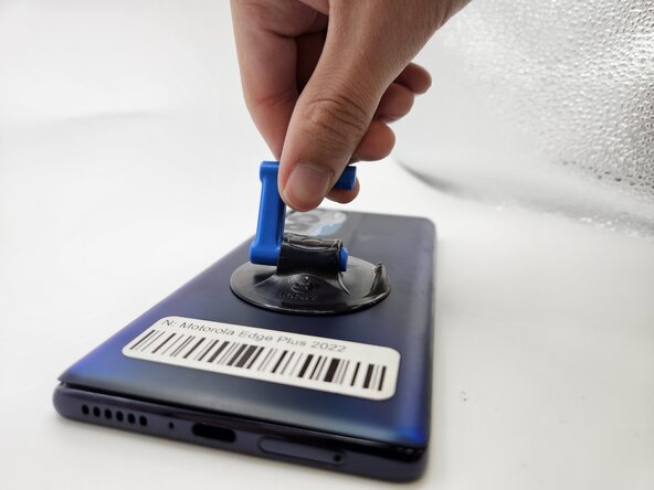
- Use an iOpener, heat gun, or hairdryer to gently heat the perimeter of the phone.
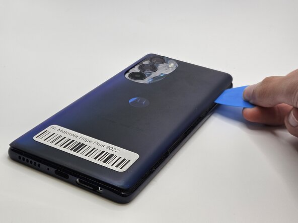
- Insert and slide the iFixit opening pick around heated edges to sever the adhesive securing the rear cover.
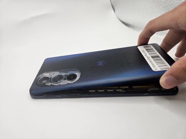
- Gently remove the back cover using the suction handle or your bare hands.
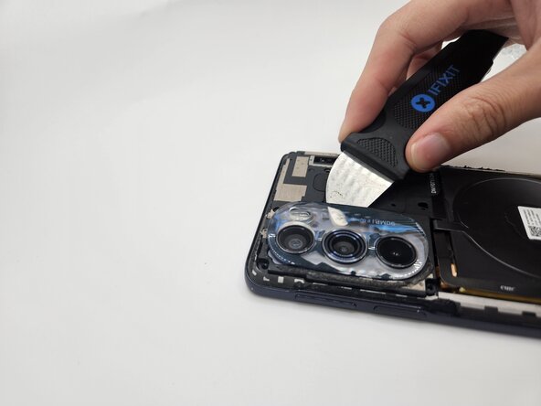
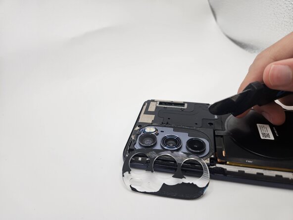
- While applying light pressure, remove the camera bezel cover by sliding the jimmy along the edges.
- Use a Phillips #00 screwdriver to remove the eleven 1.5 mm black screws.
- In case a screw gets lost, the exact specifications for all screws in this guide are OEM MOTOROLA EDGE+ PLUS 5G UW.
- Remove the logic board by lifting gently with the flat end of the spudger.
- Use the flat end of a spudger to to pry up and disconnect the two press connectors on either side of the battery.
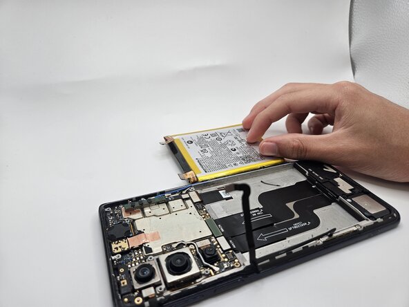
- Located in the bottom left corner of the battery, remove the tape (black in the image) with a spudger.
- Gently lift the battery up using the black spudger and remove.
- Applying too much force when removing the battery may damage it. Take care not to bend, warp, or puncture the battery.
- Apply a few drops of isopropyl alcohol if the battery is tightly adhered.
- Use a Phillips #00 screwdriver to remove the seven 5 mm screws securing the motherboard.
- Gently lift and remove the daughterboard cover.
- Insert the flat end of the spudger under each of the three press connectors and gently pry them up to disconnect them.
- Disconnect the three coaxial connectors (black, white, and blue) with tweezers by pulling them straight up.
- Use a Phillips #00 screwdriver to remove the two 1.5 mm silver screws securing the daughterboard and charging port.
- Insert the flat end of the spudger under the daughterboard piece and lift it gently to remove it.
- Insert the flat end of a spudger under the I/O board and lift to remove it.