Motherboard and Rear Cameras Removal
ID: 204793
Description: This guide shows how to remove the motherboard...
Steps:
- Let your Galaxy's battery drain below 25% before starting this repair—a charged lithium‑ion battery may catch fire if damaged.
- Unplug all cables from your phone.
- Completely power off your phone by holding the side key and volume down button and selecting Power off.
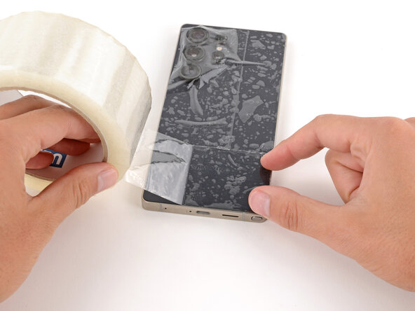
- Glass shards can complicate disassembly—or worse, cause injury. If your phone's back glass is cracked, follow this step.
- Apply strips of packing tape to the cracked glass until it's completely covered—this will help keep the glass contained and allow the suction cup to stick.
- Make sure there's a single strip (not overlapping) of tape across the bottom edge, big enough for a suction cup to fit on.
- Only cover the glass itself—don't stick any tape to the frame.
- Consider wearing safety glasses to protect your eyes from any glass shaken free during the repair.
- Adhesive secures the back cover to the frame. Heating the cover softens the adhesive, making it easier to separate.
- Heat an iOpener and lay it on the bottom edge of the back cover for two minutes.
- Alternatively, you can use a hair dryer or heat gun to heat the cover.
- Improper use of a heat gun can destroy the display and/or battery—follow the linked instructions carefully.
- While the back cover heats, note the following about its adhesive:
- The cover is secured with adhesive around the perimeter of the frame. Use this picture as a reference while you separate the adhesive.
- Only insert your tool slightly under the cover near the cameras to avoid damaging them.
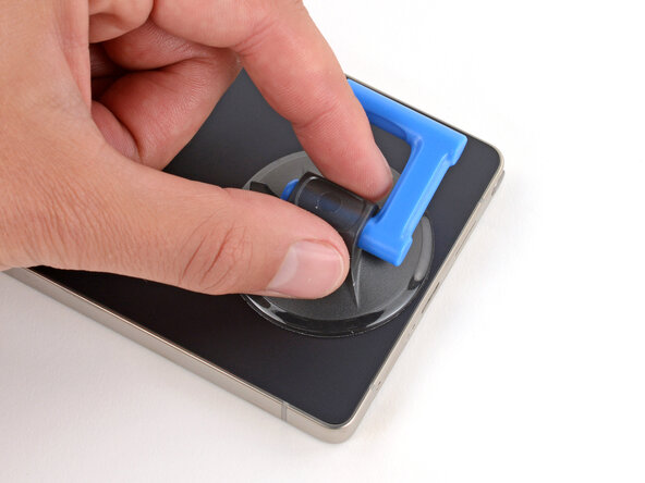
- Apply a suction handle to the center of the back cover's bottom edge, as close to the edge as possible.
- Pull up on the suction handle with strong, steady force until a gap forms between the back glass and frame.
- Use the fingers of your lifting hand to hold the phone down, or steady the frame with your free hand—be careful, your phone may be hot.
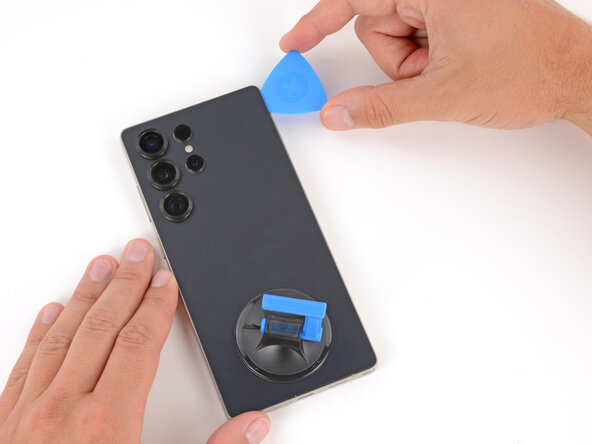
- Insert the tip of an opening pick into the gap.
- If the back cover feels stuck at any point when separating the adhesive, apply heat to the area and try again.
- Slide the opening pick along the bottom edge to separate the adhesive.
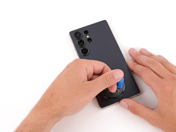
- Slide the opening pick around the bottom right corner and up the right edge to separate the adhesive.
- In the next two steps, only insert the pick slightly (a few millimeters) near the cameras to avoid damaging them.
- Slide the opening pick around the top right corner and along the top edge to separate the adhesive.
- Slide the opening pick around the top left corner and down the left edge to separate the adhesive.
- Use the suction handle to lift and remove the back cover.
- If the cover still feels stuck, go back around the perimeter with an opening pick and separate any remaining adhesive.
- During reassembly:
- This is a good point to power on your phone and test all functions before sealing it up. Be sure to power your phone back down completely before you continue working.
- Check your rear cameras for any smudges and gently wipe them with a clean, lint–free cloth if necessary.
- Your replacement back cover adhesive will be applied to either the frame or the back cover. Use cutouts and contours to see where it lines up best. If it matches the back cover, follow this guide. If it matches the frame, use this guide.
- Use the point of a spudger to pry up and disconnect the wireless charging coil press connector.
- Throughout this repair, keep track of each screw and make sure it goes back exactly where it came from to avoid damaging your phone.
- Use a Phillips screwdriver to remove the ten screws securing the wireless charging and loudspeaker assembly:
- Four 3.5 mm‑long screws securing the wireless charging coil
- Six 3.5 mm‑long screws securing the loudspeaker
- Two tabs on the right side of the wireless charging coil are secured with mild adhesive.
- Heat an iOpener and lay it on the tabs for one minute to soften the adhesive.
- During the next two steps, be very careful not to puncture or dent the battery, as it can leak dangerous chemicals or catch fire. Don’t use sharp or metal tools.
- The tabs are very fragile. If it feels like they may tear, apply more heat and try again.
- Gently slide the point of a spudger under the top edge of the upper tab and lift slowly to separate it.
- You may need to do this a few times before the tab fully separates.
- Repeat the previous step to separate the lower tab, starting at the bottom edge.
- Use the point of a spudger to pry up the right side of the loudspeaker and unclip it.
- During reassembly, press firmly around the perimeter of the loudspeaker to engage its clips.
- Use two hands to remove the wireless charging and loudspeaker assembly.
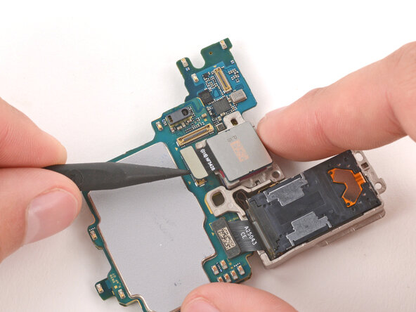
- Every press connector has a corresponding gold arrow on the board that shows the proper location to pry—nifty! Prying at the wrong location risks damaging the fragile surface‑mounted components on the board.
- Use the point of a spudger to pry up and disconnect the battery press connector.
- Use the point of a spudger to pry up and disconnect the earpiece speaker press connector (the uppermost, short one) from the top right of the motherboard.
- Use a Phillips screwdriver to remove the five 3.5 mm‑long screws securing the earpiece speaker.
- Use the point of a spudger to lift the earpiece speaker by its top left corner until it unclips.
- Be careful not to scratch the cameras with your tool.
- Remove the speaker.
- During reassembly, press firmly around the perimeter of the speaker to engage its clips.
- Be careful not to smudge the cameras or press on surface-mounted components.
- Use the point of a spudger to pry up and disconnect the two press connectors on the USB‑C board's top edge.
- Be very careful not to scrape the small surface-mounted components around the connector—only pry from its short edges to avoid damage.
- Use the point of a spudger to disconnect the interconnect cable press connector from the bottom right of the phone.
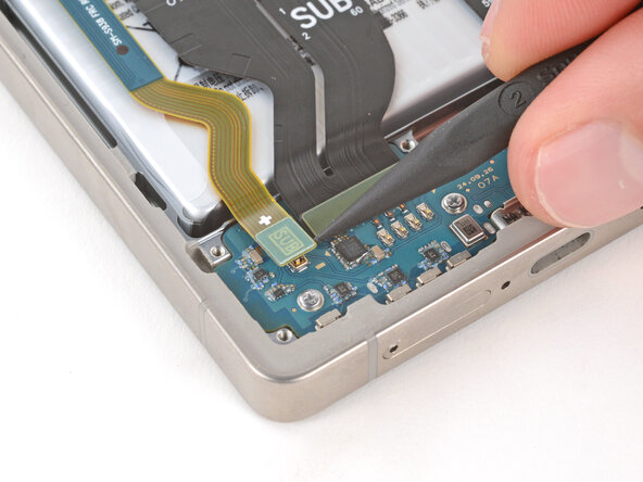
- Use the point of a spudger to pry up and disconnect the leftmost (skinny) interconnect cable's press connector from the motherboard.
- Use the point of a spudger to pry up and disconnect the wide press connector, just to the right of the previous one.
- Only pry up the connector until it disconnects, or you may damage the tape holding it in place.
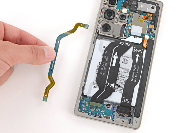
- Remove the leftmost interconnect cable.
- Grip the middle (widest) interconnect cable just above the connector near the motherboard and slowly peel it up and remove it.
- Use the point of a spudger to pry up and disconnect the screen cable press connector from the motherboard.
- Remove the screen cable.
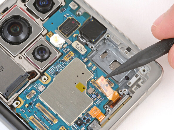
- Use the point of a spudger to pry up and disconnect the three remaining press connectors on the top and right edges of the motherboard.
- Use a Phillips screwdriver to remove the two screws securing the cameras:
- One 4.0 mm‑long black screw
- One 3.5 mm‑long silver screw
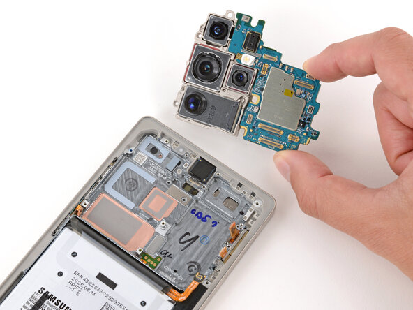
- Only grip the motherboard by its edges—not the cameras—or you risk damaging connectors and surface-mounted components.
- Lift the top edge of the motherboard and remove it, making sure no cables get snagged.
- During reassembly, slide the right edge of the board into place under the cables before laying the board down.
- You may need to hold the cables up or reposition them so they don't get stuck under the board.
- Flip the motherboard over and hold it slightly above your work surface while working on the cameras—don't press the board against your work surface, or you may damage fragile components.
- Be very careful not to scratch or smudge the cameras, as they're exposed on the bottom of the board.
- The cameras should be removed from top to bottom because of the way they're slotted into each other.
- Use the point of a spudger to pry up and disconnect the upper two press connectors for the ultrawide (uppermost) and wide (below) cameras.
- The wide and ultrawide cameras are connected and must be removed as one assembly.
- Lift the outer edge of the wide and ultrawide cameras and slide them away from the board to remove them.
- During reassembly:
- Slide the cameras into place at a slight downward angle before reconnecting them. Make sure the tab on the top edge goes under the board.
- Double-check that the cameras are properly slotted together on the bottom and top before continuing.
- Use the point of a spudger to pry up and disconnect the telephoto (middle) camera press connector.
- Lift the camera straight up and remove it.
- During reassembly, make sure the tab on the bottom edge slots into place on the other camera before reconnecting it.
- Use the point of a spudger to pry up and disconnect the periscope telephoto (bottom) camera press connector.
- Remove the camera.
- During reassembly, make sure all the cameras properly slot together. Use these photos of the bottom and top to make sure everything is in the right place—the cameras should be close together with only a slight amount of wiggle room.