Lenovo ThinkPad T480 Palm Rest Replacement
ID: 204948
Description: If you need to replace the palmrest of your...
Steps:
- Disable the battery, power down, and unplug your device before you begin.
- Flip the laptop over so the bottom of the device is showing.
- Using your fingers, slide the lock on each side of the battery to the unlocked position.
- Remove the battery from the slot.
- Use the Phillips #1 screwdriver to loosen the two screws parallel to the battery compartment.
- Open the laptop so the keyboard is facing you.
- Push the keyboard towards the screen and away from the trackpad and then slide it out towards you gently.
- The keyboard is connected to the board by two ribbon connectors.
- Be careful not to rip the connectors when you flip the keyboard over.
- Flip the keyboard over towards you to expose the backside of the keyboard and the two ribbon connectors.
- Using the black nylon spudger, flip the first ribbon connector lock open. Slide the first connector out.
- Using the black nylon spudger, unlock the second ribbon connector and slide it out from the port.
- Remove the keyboard from the laptop.
- Using the Phillips #1 screwdriver, loosen the six captive screws.
- Insert the blue plastic opening tool into the space between the lower case and the chassis.
- Slide the opening tool around the perimeter of the case to release the clips holding the case and the chassis together.
- If it feels like the battery well portion of the back cover isn't loose, these clips may be holding the cover to the laptop. Use your opening tool to pry the clips loose and try removing the cover again.
- Remove the back case.
- Use a Phillips #1 screwdriver to remove the two 4.6 mm screws that secure the internal battery to the frame.
- Not All T480 laptops come with an internal battery. If there is a spacer or nothing here, skip the next two steps.
- Use the spudger to slide the battery socket connector parallel to the motherboard and out of its socket on the motherboard.
- Lift the battery straight out of its recess and remove it.
- If the battery is difficult to remove from the recess, use a nylon spudger to gently lift it on one edge, making it easier to grasp and remove by hand.
- To prevent damage or potential fire, do not bend or flex the battery. Only use a plastic spudger and avoid any sharp tools that could puncture the battery.
- Using the Phillips #1 screwdriver remove the four 3.1 mm screws from the chassis.
- In this guide additional components have been removed. Your laptop internals will look slightly different than the images in Steps 8-10 because of this.
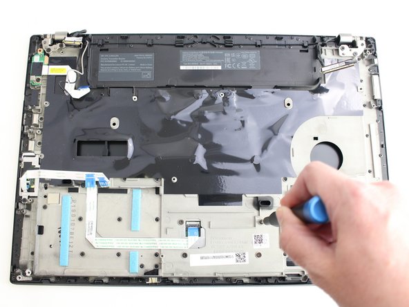
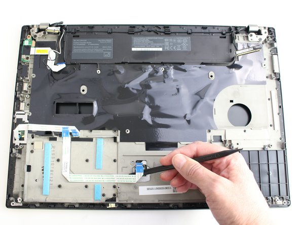
- Using the black nylon spudger, remove the ribbon cable connected to the trackpad.
- Lift the chassis up and the trackpad will fall out.
- When reinserting your trackpad, screw in the screws about halfway, and then center the trackpad. Then finish screwing them in. Otherwise, it may be off-center and might not click down.
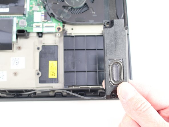
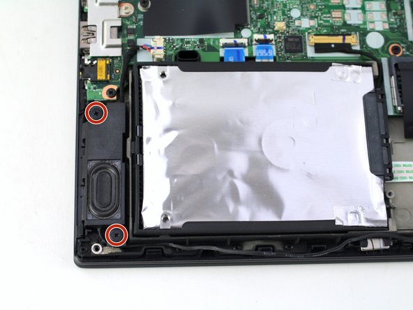
- Using the Phillips #1 screwdriver, remove two 4.8 mm screws from the right speaker.
- Lift the right speaker out of the case.
- Gently remove the speaker cable from the perimeter of the chassis, connecting the right speaker to the left speaker.
- Remove two 4.8 mm screws from the left speaker using the Phillips #1 screwdriver.
- Using the black nylon spudger, remove the slide connector which attaches the left speaker to the motherboard.
- Remove the left speaker from the case.
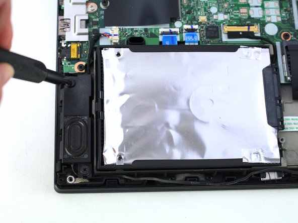
- Using the black nylon spudger, lift the connector lock up.
- Disconnect the storage cable from the system board.
- Lift the hard drive up with a tab if it has one or with your spudger.
- Lift the drive assembly from the system.
- Using the Phillips #1 screwdriver, remove three 4.6 mm screws from the I/O bracket.
- Lift the I/O bracket off the motherboard.
- Using the Phillips #1 screwdriver, remove the three 4.1 mm screws from the RJ45 bracket.
- Lift the bracket off of the motherboard.
- Use the black nylon spudger to lift up the small locking flap on the power button cable's ZIF connector.
- Slide the power button cable out of the ZIF connector.
- Using the black nylon spudger, disconnect the LCD cable from the motherboard.
- Use the tip of a spudger or an opening tool, to flip up the small, hinged locking flap on the camera cable connector to remove the cable from the motherboard.
- Using the black nylon spudger, remove the NFC cable connector and trackpad connector from the motherboard.
- Using the Phillips #1 screwdriver, remove seven 3.6 mm screws from the motherboard.
- Lift the motherboard off of the case to remove it.
- Remove the cables from the cable guides.
- Using the Phillips #1 screwdriver, remove two 4.3 mm screws from each hinge (four total).
- In this image, all of the internal components were removed prior to this step so your device will look somewhat different.
- Lift the keyboard bezel up and slide it out from the hinges to separate it from the LCD assembly.
- In this image, all of the internal components were removed prior to this step so your device will look somewhat different.
- Remove the trackpad ribbon from the old palm rest and move it to the same spot on the new one. Pull it up carefully and glue it down or use kapton tape.
- Unscrew the two screws in the smart card reader and remove it