How to Install the Dual M.2 Adapter in the Framework Laptop 16
ID: 205708
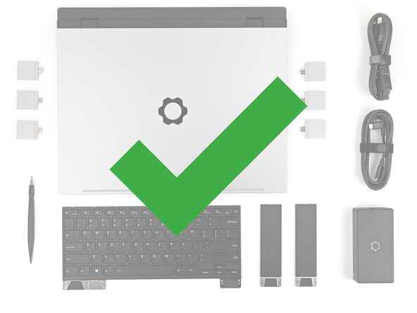
Description: Use this guide to install the Dual M.2 Adapter...
Steps:
- Unplug all cables and fully shut down your laptop.
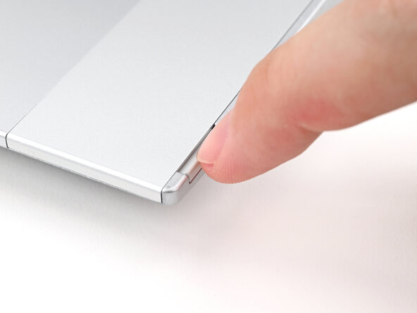
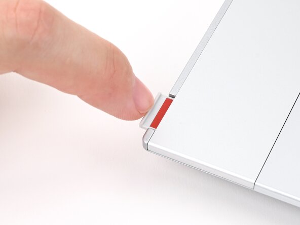
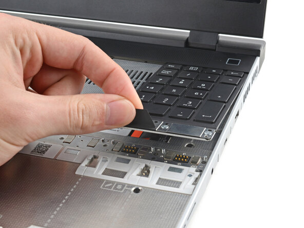
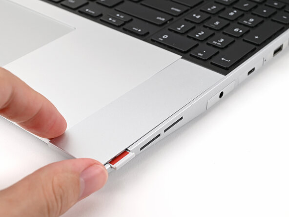
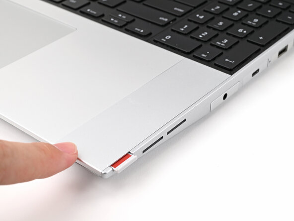
- Use your fingernail to pull out the two Input Module latches and unlock them.
- The latch will show red if it's unlocked.
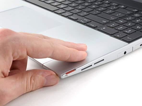
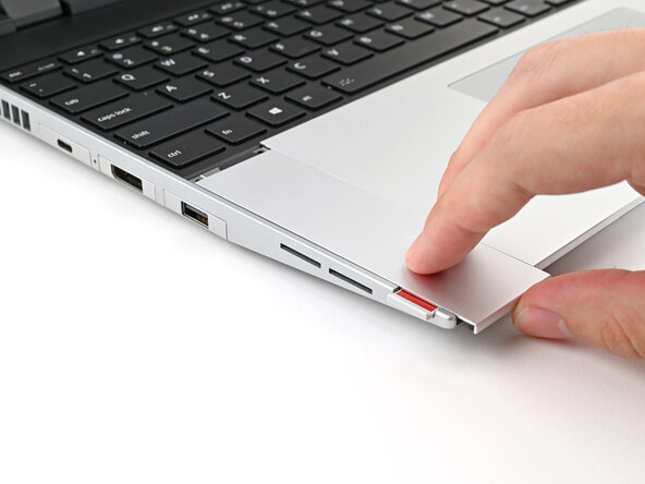
- Use your fingers to slide the Touchpad Spacer toward the bottom edge of the laptop and unclip it.
- If you're having trouble, check if the corresponding Input Module latch is properly unlocked.
- Lift the Touchpad Spacer off the laptop and remove it.
- Repeat the same procedure for the other touchpad spacer.
- Use your fingers to slide the Touchpad Module toward the bottom edge of the laptop and disconnect it.
- If you're having trouble, check if the Input Module latches are properly unlocked.
- Lift the Touchpad Module and remove it.
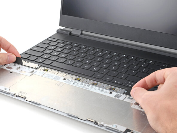
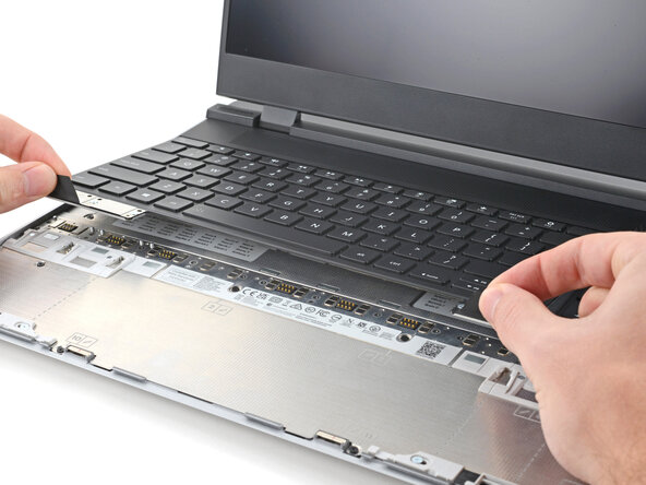
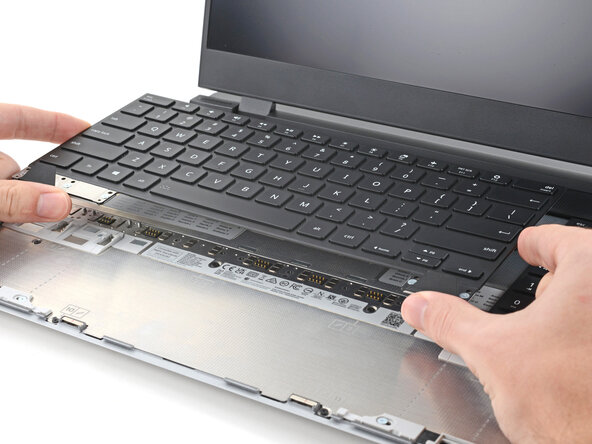
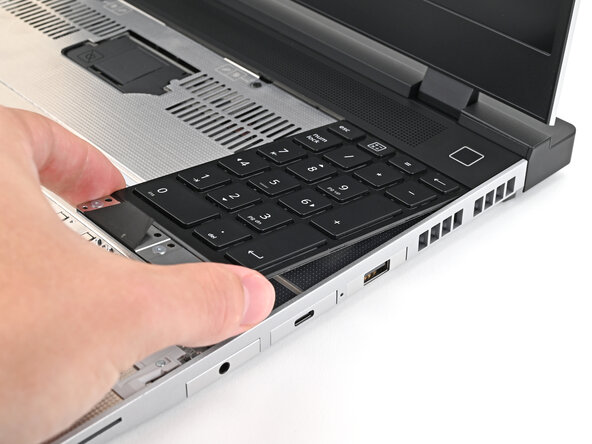
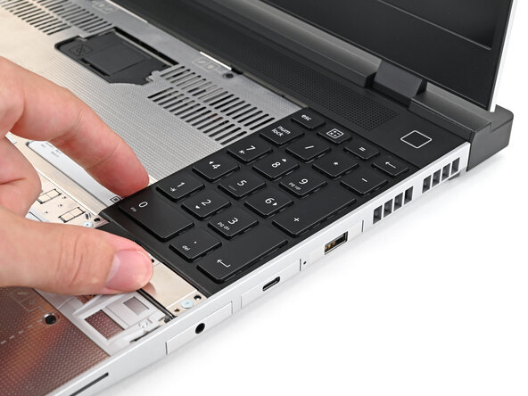
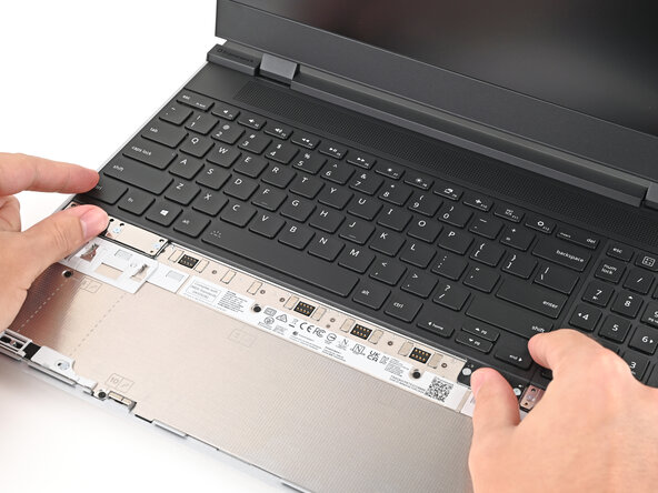
- The keyboard is held in place with strong magnets. Apply gradually increasing force to avoid having the keyboard violently eject.
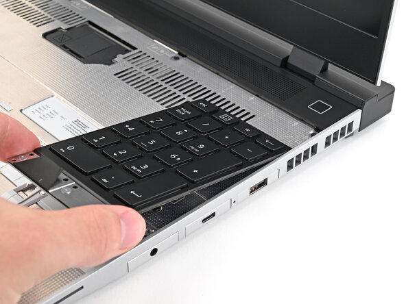
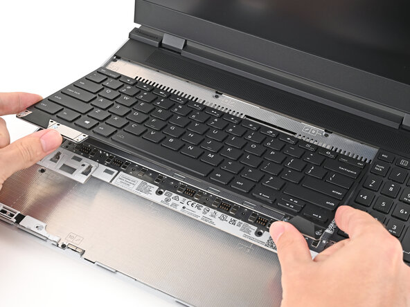
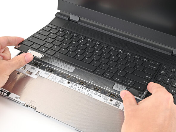
- Grip the two pull tabs along the bottom of the keyboard and lift until its magnets release.
- Remove the keyboard.
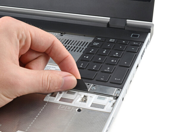
- Your Input Module(s) might be different, but the procedure to remove them is the same.
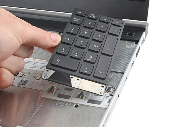
- Grip the pull tab at the bottom of the Input Module and lift until its magnets release.
- Remove the Input Module.
- Repeat for any remaining Input Modules.
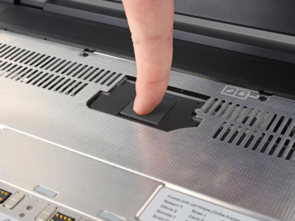
- Lift the interposer door by its black pull tab and let it rest upright.
- Use your Framework Screwdriver to loosen the three captive T5 Torx screws securing the interposer.
- Lift the interposer by its pull tab and remove it.
- Use your Framework Screwdriver to loosen the two captive T5 Torx screws securing the Expansion Bay Shell.
- Close the interposer door before continuing.
- Close your laptop and flip it over.
- Slide the Expansion Bay Shell out of the laptop and remove it.
- The shell should slide out easily. If you feel any resistance, check that the screws holding it in place are fully loosened.
- Use the flat end of your Framework Screwdriver, or a clean fingernail, to lift up and release the locking tab on one of the fan ZIF connectors.
- Use your fingers to grip the brown pull tab and slide the fan cable straight out of its socket.
- Repeat the previous two steps to disconnect the other fan cable.
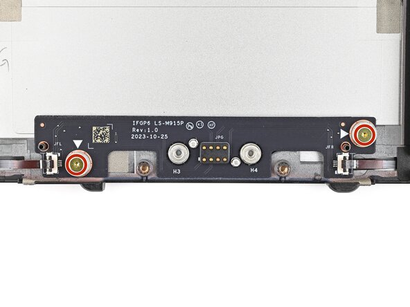
- Use your Framework Screwdriver to remove the two 3.6 mm‑long screws securing the Expansion Bay Shell Fan Board.
- Hold on to these screws—you'll use them to install the Dual M.2 Adapter.
- Use your fingers to lift the board straight off its alignment pegs on Expansion Bay Shell and remove it.
- Use your Framework Screwdriver to remove the three 3.6 mm‑long screws securing the rubber spacer.
- Hold on to these screws—you'll use them to install the Dual M.2 Adapter.
- While holding the Expansion Bay Shell down, use the flat end of your Framework Screwdriver to push the plastic strip near the rubber spacer outwards.
- While keeping the plastic strip bent, lift the rubber spacer out of its screw posts and remove it.
- Congratulations on completing disassembly! The remaining steps will show how to reassemble your Framework Laptop.
- Flip over your Dual M.2 Adapter and locate the marked section where you'll place the 1.75 mm thermal pad.
- When placing the thermal pad, make sure you don't cover the screw holes.
- Once you place the thermal pad, it's difficult to peel it off and move it without damaging it. Take your time and work slowly to ensure it's aligned properly.
- Remove the clear liner from the thermal pad labeled 1.75 mm to expose one side of it.
- Place the thermal pad over its spot on the back of the adapter.
- If you have trouble handling your thermal pad, you can store it in your fridge for a few minutes to make it more rigid.
- Use your finger to gently press the thermal pad onto the adapter.
- Remove the blue liner to expose its top side.
- Once you place the Dual M.2 Adapter, it's difficult to remove it without damaging the thermal pad. Take your time and work slowly to ensure the adapter is aligned properly.
- Flip over the adapter and place it into its spot in the Expansion Bay Shell, making sure it slots into its alignment pegs.
- Before continuing, make sure the fan cables aren't trapped under the adapter.
- Use your Framework Screwdriver to partially install the four 3.6 mm‑long screws securing the Dual M.2 Adapter—only screw them in a few turns.
- Tighten the four screws in an "X" pattern starting with the top left screw.
- Only tighten the screws a few turns at a time to evenly compress the thermal pad.
- In order: top left → bottom right → bottom left → top right
- Use your fingers to grip the brown pull tab and slide the right fan cable straight into its socket.
- Use the flat end of your Framework Screwdriver, or a clean fingernail, to press down the locking tab on the right fan ZIF connector.
- Repeat the previous step for the left fan.
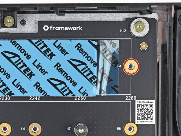
- Depending on the size of your SSD, you may need to change the screw position and cut down the included thermal pad to fit the SSD.
- Refer to the markings on the adapter to figure out where your SSD will go:
- 2230 SSDs → H1 or H5
- 2242 SSDs → H2 or H6
- 2260 SSDs → H3 or H7
- 2280 SSDs → H4 or H8
- Use your Framework Screwdriver to remove one or both of the 6.7 mm‑long T5 Torx SSD screws, depending on how many SSDs you're installing.
- The next six steps will show how to install a 2280 SSD. If you're installing anything smaller, skip to this step.
- If you're installing a single‑sided SSD (chips on only one side), grab the 2.25 mm thermal pad.
- If you're installing a double‑sided SSD (chips on both sides), grab the 1.25 mm thermal pad.
- Without removing any liners, place the thermal pad over the slot where you want to install your SSD.
- Orient the thermal pad so it sits between the small components next to the SSD's socket and the screw hole—including the gold ring around it.
- When you're confident in how your thermal pad should be oriented, remove it and continue to the next step.
- Remove the clear liner from the thermal pad to expose one side of it.
- Place the thermal pad over its spot on the adapter.
- Use your finger to gently press the thermal pad onto the adapter.
- Remove the blue liner to expose its top side.
- Hold the SSD by its edges. Don't touch the gold contacts with your fingers. If you do, wipe the contacts with a clean, lint-free cloth to remove any finger oils.
- Insert the SSD into the socket at a shallow angle. The gold contacts should mostly be covered by the socket.
- The SSD fits into the socket in one orientation. If it doesn't feel like it fits, try flipping the module.
- While lightly pressing the SSD into the thermal pad, guide the gap in the SSD screw into the notch on back of the SSD
- The head of the screw should completely cover the notch and its threads should slot into the adapter's screw hole.
- Use your Framework Screwdriver to install the 6.7 mm‑long screw securing the SSD.
- Only tighten the screw until it feels snug. If your SSD is bending, then loosen the screw until the SSD sits flat.
- The next seven steps will show how to install an SSD that's 2260 or smaller (in this case a 2230).
- If you're installing a single‑sided SSD (chips on only one side), grab the 2.25 mm thermal pad.
- If you're installing a double‑sided SSD (chips on both sides), grab the 1.25 mm thermal pad.
- Without removing any liners, place the thermal pad over the slot where you want to install your SSD.
- Orient the thermal pad so it sits near the small components next to the SSD's socket.
- Use a marker to indicate where you need to cut the thermal pad so it fits between the socket and your SSD's screw hole—including the gold ring around it.
- Use the SSD size numbers to judge where the screw holes and its contacts are located. The screw holes are slightly to the left of its number.
- When you're confident in how your thermal pad should be oriented, remove it and continue to the next step.
- Use scissors to cut the thermal pad to your desired length.
- Remove the clear liner from the thermal pad to expose one side of it.
- Place the thermal pad over its spot on the adapter.
- Use your finger to gently press the thermal pad onto the adapter.
- Remove the blue liner to expose its top side.
- Hold the SSD by its edges. Don't touch the gold contacts with your fingers. If you do, wipe the contacts with a clean, lint-free cloth to remove any finger oils.
- Insert the SSD into the socket at a shallow angle. The gold contacts should mostly be covered by the socket.
- The SSD fits into the socket in one orientation. If it doesn't feel like it fits, try flipping the module.
- While lightly pressing the SSD into the thermal pad, guide the gap in the SSD screw into the notch on back of the SSD
- The head of the screw should completely cover the notch and its threads should slot into the adapter's screw hole.
- Use your Framework Screwdriver to install the 6.7 mm‑long screw securing the SSD.
- Only tighten the screw until it feels snug. If your SSD is bending, then loosen the screw until the SSD sits flat.
- Align the Expansion Bay Shell with its slot in the laptop.
- Check that the shell sits evenly with the rail on the outside edges of the slot.
- Check that the two center rails are threaded between the fans.
- While keeping the shell level with the laptop, slide it into its slot.
- The shell should slide in easily. If you feel any resistance, pull the module out and realign it.
- You should hear an audible "click" when the shell's clips snap into place.
- Flip over the laptop and open it.
- Lift the interposer door by its black pull tab and let it rest upright.
- Use your Framework Screwdriver to tighten the two captive T5 Torx screws securing the Expansion Bay Shell.
- Place the interposer over its spot between the Mainboard and the Expansion Bay.
- Use your Framework Screwdriver to tighten the three captive T5 Torx screws securing the interposer.
- Close the interposer door.
- Your Input Module(s) might be different, but the procedure to remove them is the same.
- Align the top edge of the Input Module with the top edge of the laptop.
- Lay the Input Module on the laptop and let the magnets pull the keyboard into place
- Make sure the Input Module is seated properly on its alignment pegs and sits flush with the edges of the laptop.
- Repeat for any remaining Input Modules.
- Align the top edge of the keyboard with the top edge of the laptop.
- Lay the keyboard on the laptop and let the magnets pull the keyboard into place
- Make sure the keyboard is seated properly on its alignment pegs and sits flush with the edges of the laptop.
- Place the Touchpad Module flat on its cutout so its clips are properly aligned.
- Press the Touchpad Module down and slide it into place so it lines up evenly with the bottom edge of the laptop.
- Place the Touchpad Spacer over its spot on the laptop with the bottom edge overhanging slightly.
- Slide the Touchpad Spacer towards the top of the laptop to secure it.
- Repeat the same procedure for the other Touchpad Spacer.