How to Replace the Graphics Module Thermal Pad in your Framework Laptop 16
ID: 205712
Description: Use this guide to replace the thermal pad in...
Steps:
- Unplug all cables and fully shut down your laptop.
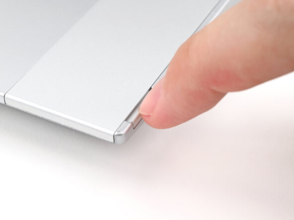
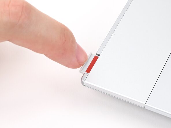
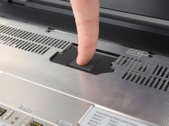
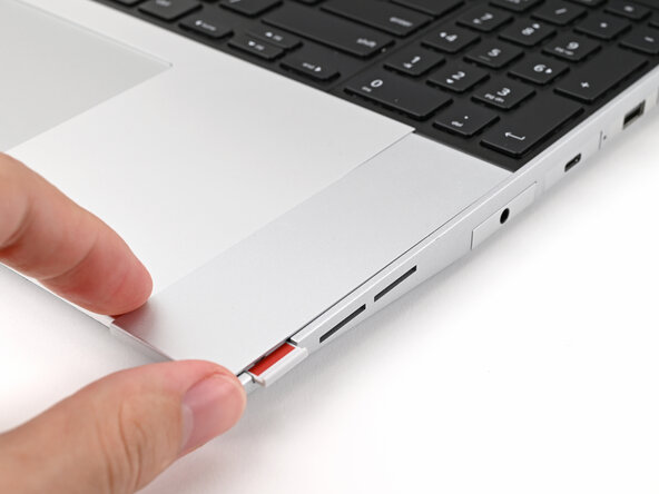
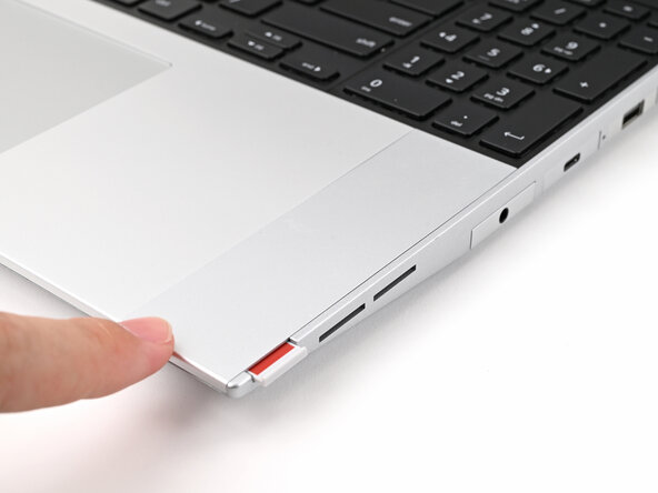
- Use your fingernail to pull out the two Input Module latches and unlock them.
- The latch will show red if it's unlocked.
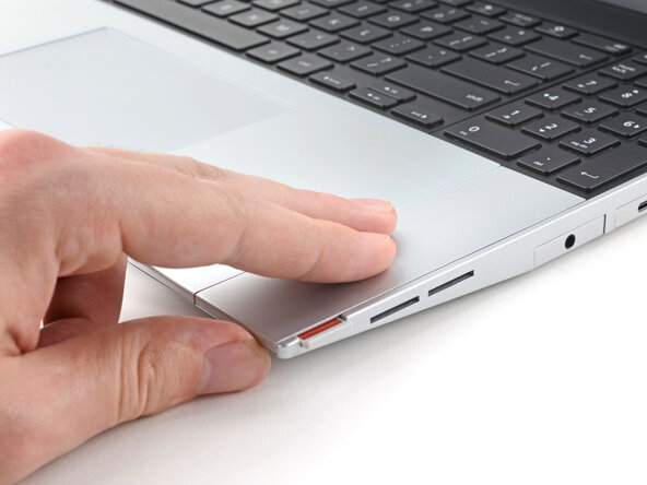
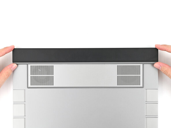
- Use your fingers to slide the Touchpad Spacer toward the bottom edge of the laptop and unclip it.
- If you're having trouble, check if the corresponding Input Module latch is properly unlocked.
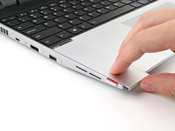
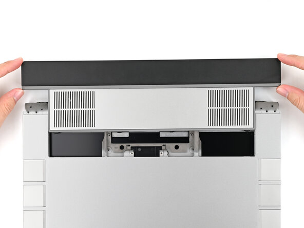
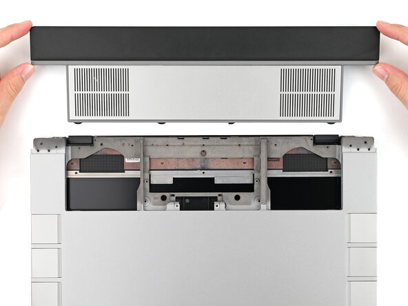
- Lift the Touchpad Spacer off the laptop and remove it.
- Repeat the same procedure for the other touchpad spacer.
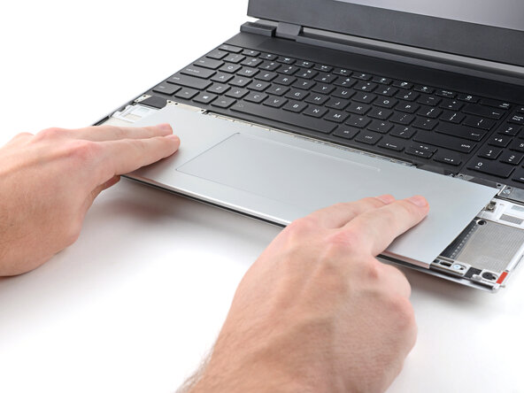
- Use your fingers to slide the Touchpad Module toward the bottom edge of the laptop and disconnect it.
- If you're having trouble, check if the Input Module latches are properly unlocked.
- Lift the Touchpad Module and remove it.
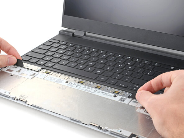
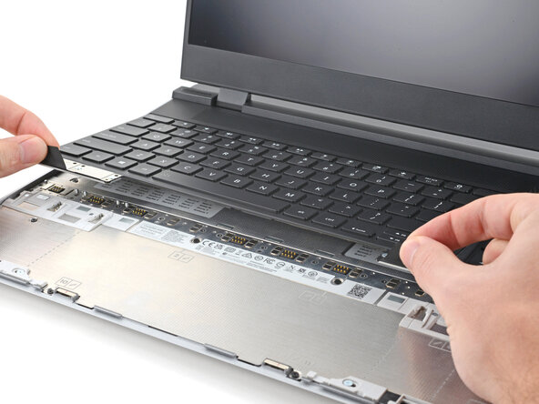
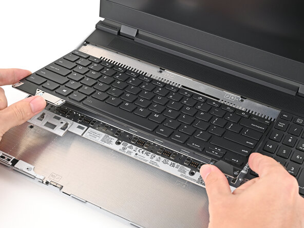
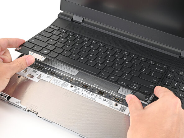
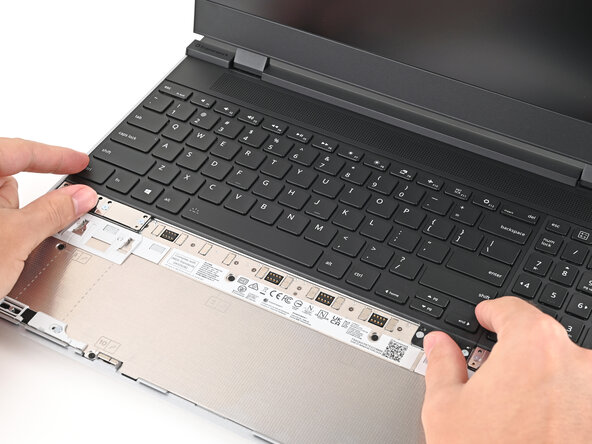
- The keyboard is held in place with strong magnets. Apply gradually increasing force to avoid having the keyboard violently eject.
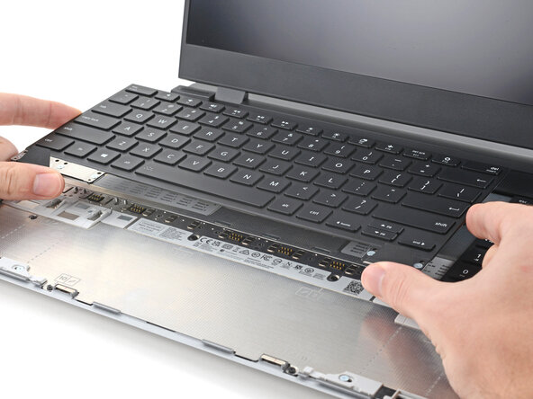
- Grip the two pull tabs along the bottom of the keyboard and lift until its magnets release.
- Remove the keyboard.
- Your Input Module(s) might be different, but the procedure to remove them is the same.
- Grip the pull tab at the bottom of the Input Module and lift until its magnets release.
- Remove the Input Module.
- Repeat for any remaining Input Modules.
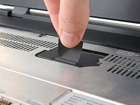
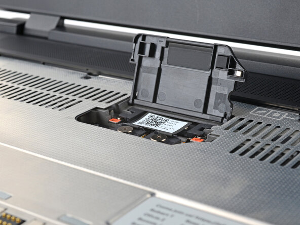
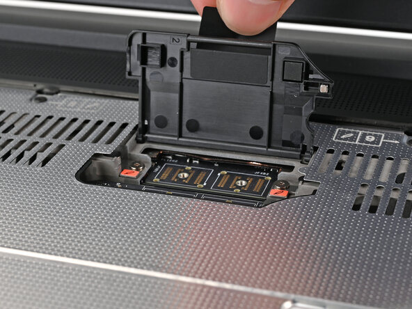
- Lift the interposer door by its black pull tab and let it rest upright.
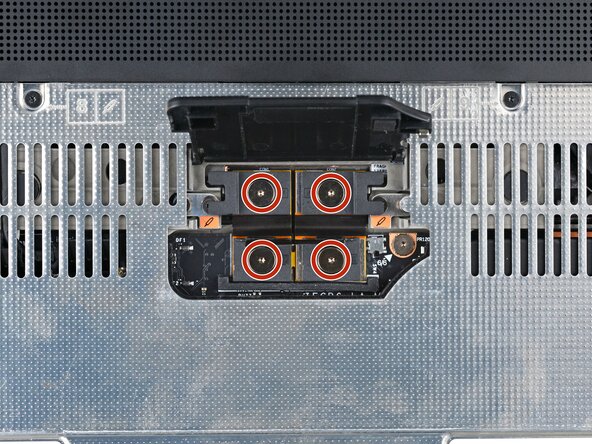
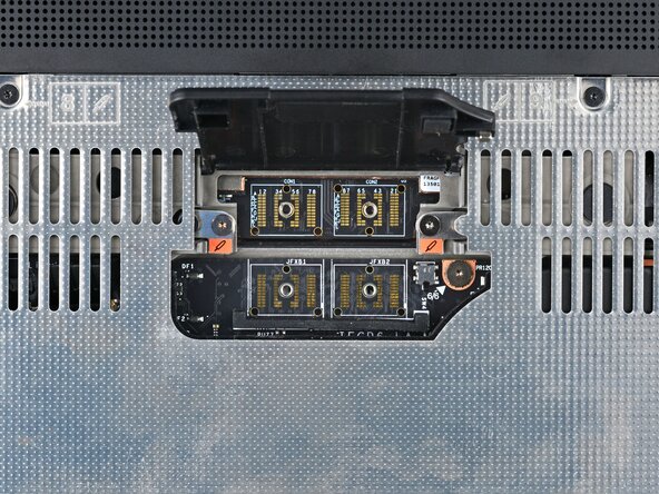
- Use your Framework Screwdriver to loosen the four captive T5 Torx screws securing the interposer.
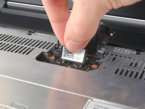
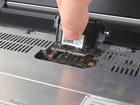
- Lift the interposer by its pull tab and remove it.
- Use your Framework Screwdriver to loosen the two captive T5 Torx screws securing the Graphics Module.
- Close the interposer door before continuing.
- Close your laptop and flip it over.
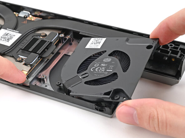
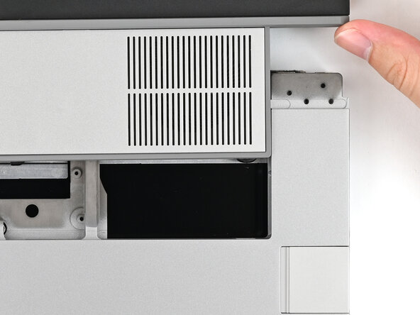
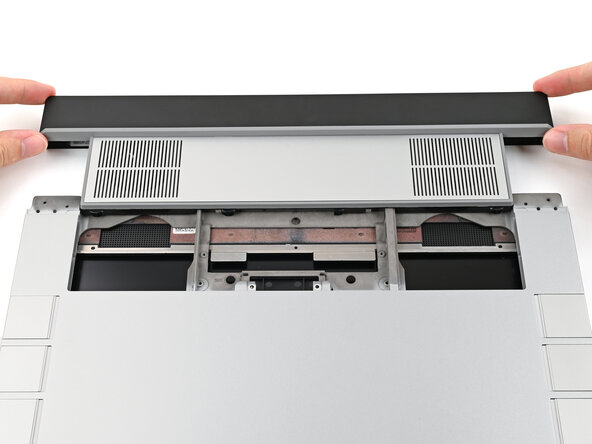
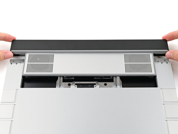
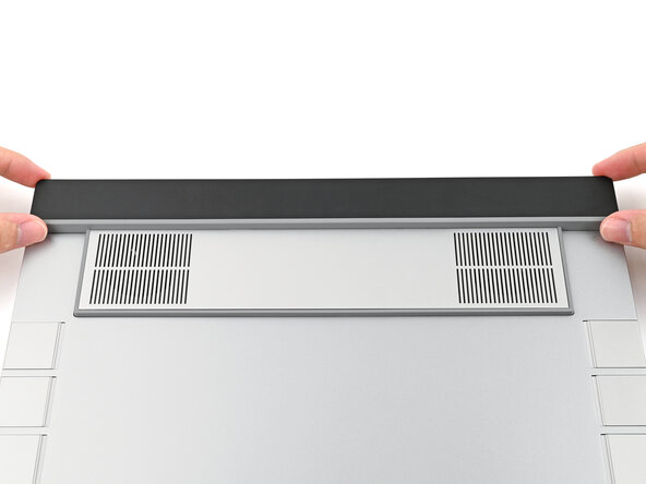
- Slide the Graphics Module out of the laptop and remove it.
- The module should slide out easily. If you feel any resistance, check that the screws holding it in place are fully loosened.
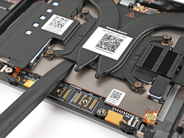
- There are two models of Graphics Modules:
- NVIDIA® GeForce RTX™ 5070 (first photo)
- AMD Radeon™ RX 7700S (second photo)
- There are slight visual differences between the models, but the disassembly procedure is the same.
- Use your Framework Screwdriver to remove the four 3.6 mm‑long T5 Torx screws securing the Graphics Module cover:
- Two screws on the flat surface of the module, next to the fans.
- Two screws on the thin edge of the module, near the ends. You'll need to flip the module on its back edge to access them.
- Use your fingers to lift the cover off the Graphics Module and remove it.
- Use the flat end of a spudger, or a clean fingernail, to lift up and release the locking tab on the left fan ZIF connector.
- Use your fingers to grip the brown pull tab and slide the fan cable straight out of its socket.
- Use a T5 Torx screwdriver to loosen the four captive screws securing the left fan.
- Use one hand to press the fan cable flat to the module.
- Use your other hand to pull the fan out of its housing, making sure to thread the cable though its slot.
- Remove the fan.
- Use the flat end of a spudger, or a clean fingernail, to lift up and release the locking tab on the right fan ZIF connector.
- Use your fingers to grip the brown pull tab and slide the fan cable straight out of its socket.
- Use a T5 Torx screwdriver to loosen the four captive screws securing the right fan.
- Use one hand to press the fan cable flat to the module.
- Use your other hand to pull the fan out of its housing, making sure to thread the cable though its slot.
- Remove the fan.
- The screw configuration will look different depending on your Graphics Module, but the procedure is the same.
- Use your Framework Screwdriver to loosen the captive T5 Torx screws securing the Graphics Module Heatsink:
- Loosen the captive screw at the bottom left corner of the heatsink.
- Loosen the captive screws directly over the GPU in order from 1–4 (the numbers are engraved on the metal near the screw).
- Use the flat end of the Framework Screwdriver to pry up the flat metal plate under the heat pipes until you feel the thermal pads separate.
- Don't pry under the heat pipes as you risk bending them.
- Grip the edges of the heatsink, near its curved pipes, and lift it straight up to remove it.
- Congratulations on completing disassembly! The remaining steps will show how to reassemble your Framework Laptop.
- Your Graphics Module will have either a thermal pad or thermal paste. Follow the procedure normally to remove either compound.
- Use a few drops of high concentration (>90%) isopropyl alcohol and a lint-free cloth to wipe away the thermal compound residue.
- Repeat the previous step for the thermal compound residue on the bottom of the heatsink.
- Peel off the clear liner from the thermal pad to expose one side of it.
- Place the exposed side of the thermal pad over the CPU.
- If you have trouble handling your thermal pad, you can store it in your fridge for a few minutes to make it more rigid.
- Use your finger to lightly press the thermal pad to the GPU and bond it.
- Remove the green liner from the thermal pad to expose its top side.
- Align your heatsink over the CPU and place it straight down onto the Mainboard.
- The thermal pad needs to go through a few thermal cycles before it gets to full performance.
- The screw configuration will look different depending on your Graphics Module, but the procedure is the same.
- Use your Framework Screwdriver to tighten the captive T5 Torx screws securing the Graphics Module Heatsink:
- Tighten the captive screws directly over the GPU in order from 4–1.
- Tighten the captive screw at the bottom left corner of the heatsink.
- Place the right fan onto the Expansion Bay Shell, making sure to thread the cable through its slot.
- Use a T5 Torx screwdriver to tighten the four captive screws securing the right fan.
- Use your fingers to grip the brown pull tab and slide the right fan cable straight into its socket.
- Use the flat end of your Framework Screwdriver, or a clean fingernail, to press down the locking tab on the fan ZIF connector.
- Place the left fan onto the Expansion Bay Shell, making sure to thread the cable through its slot.
- Use a T5 Torx screwdriver to tighten the four captive screws securing the left fan.
- Use your fingers to grip the brown pull tab and slide the left fan cable straight into its socket.
- Use the flat end of your Framework Screwdriver, or a clean fingernail, to press down the locking tab on the fan ZIF connector.
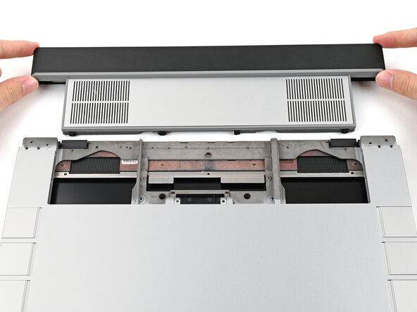
- Place the cover over its slot on the Graphics Module.
- Use your Framework Screwdriver to install the four 3.6 mm‑long T5 Torx screws securing the Graphics Module cover:
- Two screws on the flat surface of the module, next to the fans.
- Two screws on the thin edge of the module, near the ends. You'll need to flip the module on its back edge to access them.
- Align the Graphics Module with its slot in the laptop.
- Check that the module sits evenly with the rail on the outside edges of the slot.
- Check that the two center rails are threaded between the fans.
- When installing the module, keep it level to the laptop so it doesn't buckle on the rails.
- There should be no gaps between the laptop and the module when it's installed correctly.
- While keeping the module level with the laptop, slide it into its slot.
- The module should slide in easily. If you feel any resistance, pull the module out and realign it.
- You should hear an audible "click" when the module's clips snap into place.
- Flip over the laptop and open it.
- Lift the interposer door by its black pull tab and let it rest upright.
- Use your Framework Screwdriver to tighten the two captive T5 Torx screws securing the Graphics Module.
- Place the interposer over its spot between the Mainboard and the Graphics Module.
- Use your Framework Screwdriver to tighten the four captive T5 Torx screws securing the interposer.
- Close the interposer door.
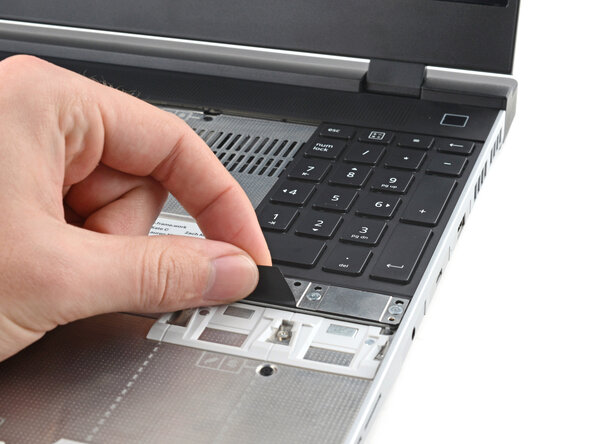
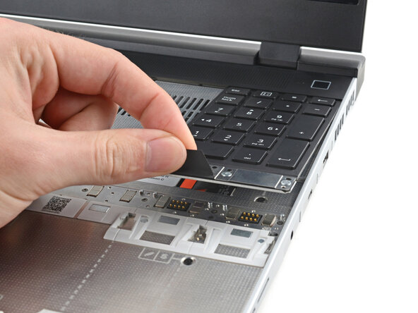
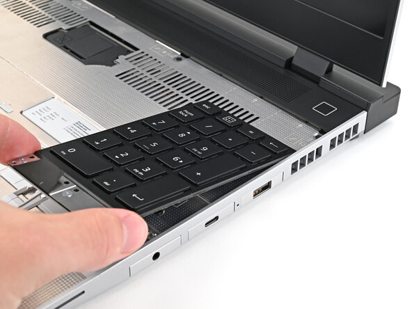
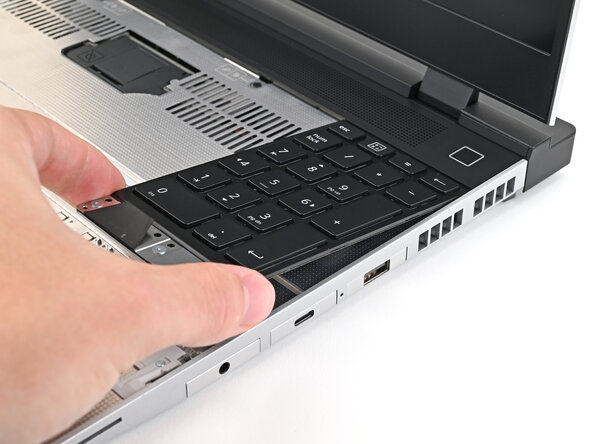
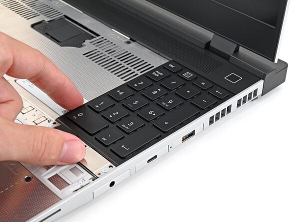
- The numpad is held in place with strong magnets. Apply gradually increasing force to avoid having the numpad violently eject.
- Grip the pull tab at the bottom of the numpad.
- Lift the pull tab until the numpad magnets release.
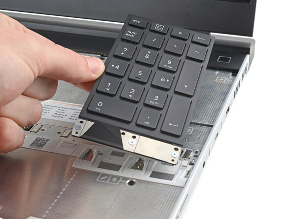
- Remove the numpad.
- During reassembly, make sure the numpad is seated properly on its alignment pegs and sits flush with the edges of the laptop.
- Align the top edge of the keyboard with the top edge of the laptop.
- Lay the keyboard on the laptop and let the magnets pull the keyboard into place
- Make sure the keyboard is seated properly on its alignment pegs and sits flush with the edges of the laptop.
- Place the Touchpad Module flat on its cutout so its clips are properly aligned.
- Press the Touchpad Module down and slide it into place so it lines up evenly with the bottom edge of the laptop.
- Place the Touchpad Spacer over its spot on the laptop with the bottom edge overhanging slightly.
- Slide the Touchpad Spacer towards the top of the laptop to secure it.
- Repeat the same procedure for the other Touchpad Spacer.