SRAM GX Eagle Transmission Derailleur Pogo Pin Replacement
ID: 206086
Description: If your SRAM AXS electronic derailleur doesn't...
Steps:
- Begin by removing the derailleur from the bike. As covered in the video SRAM GX and S1000 Eagle Transmission Rear Derailleur Rebuild, remove the:
- pulley cage and damper assembly
- You can remove the pulley cage with the chain still attached by rotating the derailleur body counter-clockwise.
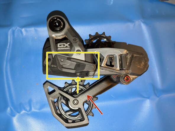
- skid plate (one 2mm allen screw)
- upper and lower parts of the outer parallelogram link (two 2.5mm allen bolts)
- The P-Knuckle contains a strong spring that can move unexpectedly, pinch, or stab you. Use caution when removing and reinstalling.
- The spring is under the least tension when the derailleur is shifted fully inboard to the largest/easiest gear. If you can still power your derailleur, shift into this position by repeatedly double-tapping the AXS button.
- Undo the two 2.5mm security allen bolts and carefully pull the lower and then upper halves of the inner parallelogram link off.
- When reassembling, slip the metal arm from the motor under the spring before sliding the upper half of the inner link into place.
- Remove the upper arms, small white bushing, pivot axles, and GX nameplate from the motor case.
- Take careful note of where each bolt belongs, they are all slightly different!
- When reassembling, it is helpful to get everything else loosely in place before wiggling the name plate into position.
- Remove the plastic shields on the bottom of the motor case and around the AXS button.
- You can test the derailleur at this point by holding a battery against the pogo pins and pressing the AXS button. If a green light appears and the derailleur moves, congrats - you fixed it!
- Remove the torx screws holding the two halves of the motor case together.
- Take steps to avoid electrostatic discharge!
- Take care not to drop or move any of the small gears.
- Remove the circuit board from the white plastic clip.
- Unplug the motor cable by gently lifting the white connector up from the circuit board.
- Remove the rubber sleeves around the pogo pins and note their orientation.
- Take care not to damage or bridge nearby components.
- Remove and replace all damaged pogo pins. Make sure the new pogo pins are fully seated and straight.