Samsung Galaxy S25 FE USB-C Board Replacement
ID: 206301
Description: Follow this guide to replace the USB-C board...
Steps:
- Let your Galaxy's battery drain below 25% before starting this repair—a charged lithium‑ion battery may catch fire if damaged.
- Unplug all cables from your phone.
- Completely power off your phone by holding the side key and volume down button and selecting Power off.
- Glass shards can complicate disassembly—or worse, cause injury. If your phone's back glass is cracked, follow this step.
- Apply strips of packing tape to the cracked glass until it's completely covered—this will help keep the glass contained and allow the suction cup to stick.
- Make sure there's a single strip (not overlapping) of tape across the bottom edge, big enough for a suction cup to fit on.
- Only cover the glass itself—don't stick any tape to the frame.
- Consider wearing safety glasses to protect your eyes from any glass shaken free during the repair.
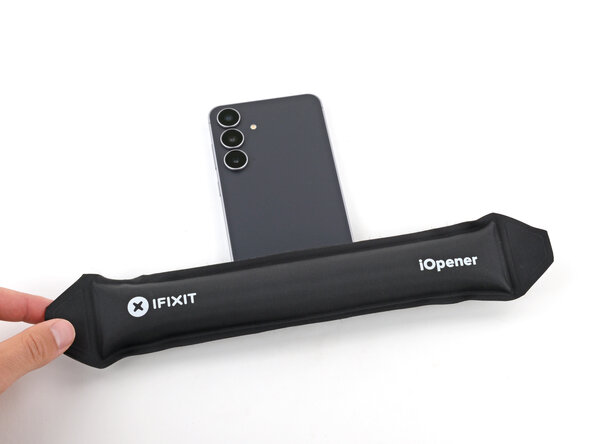
- Adhesive secures the back cover to the frame. Heating the cover softens the adhesive, making it easier to separate.
- Heat an iOpener and lay it on the bottom edge of the back cover for two minutes.
- Alternatively, you can use a hair dryer or heat gun to heat the cover.
- Improper use of a heat gun can destroy the display and/or battery—follow the linked instructions carefully.
- While the back cover heats, note the following about its adhesive:
- The cover is secured with adhesive around the perimeter of the frame. Use this picture as a reference while you separate the adhesive.
- Only insert your tool slightly under the cover near the cameras to avoid damaging them.
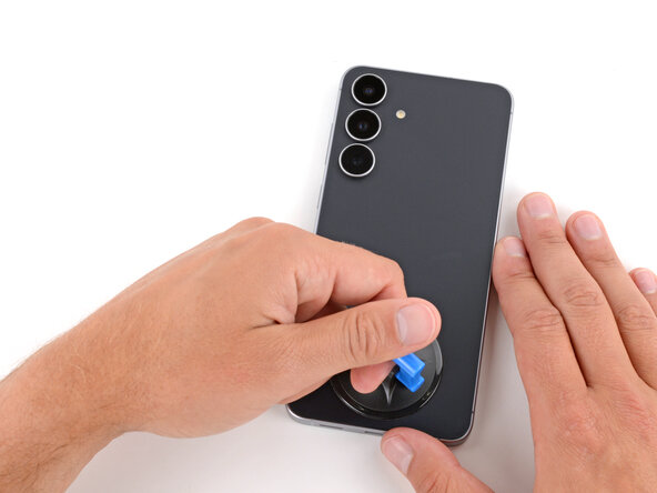
- Apply a suction handle to the center of the back cover's bottom edge, as close to the edge as possible.
- Pull up on the suction handle with strong, steady force until a gap forms between the back cover and frame.
- Use the fingers of your lifting hand to hold the phone down, or steady the frame with your free hand—be careful, your phone may be hot.
- Insert the tip of an opening pick into the gap.
- If the back cover feels stuck at any point when separating the adhesive, apply heat to the area and try again.
- Slide the opening pick along the bottom edge to separate the adhesive.
- Slide the opening pick around the bottom right corner and up the right edge to separate the adhesive.
- In the next two steps, only insert the pick slightly (a few millimeters) near the cameras to avoid damaging them.
- Slide the opening pick around the top right corner and along the top edge to separate the adhesive.
- Slide the opening pick around the top left corner and down the left edge to separate the adhesive.
- Use the suction handle to lift and remove the back cover.
- If the cover still feels stuck, go back around the perimeter with an opening pick and separate any remaining adhesive.
- During reassembly:
- This is a good point to power on your phone and test all functions before sealing it up. Be sure to power your phone back down completely before you continue working.
- Check your rear cameras for any smudges and gently wipe them with a clean, lint–free cloth if necessary.
- Your replacement back cover adhesive will be applied to either the frame or the back cover. Use cutouts and contours to see where it lines up best. If it matches the back cover, follow this guide. If it matches the frame, use this guide.
- Use the point of a spudger to pry up and disconnect the wireless charging coil press connector.
- Throughout this repair, keep track of each screw and make sure it goes back exactly where it came from to avoid damaging your phone.
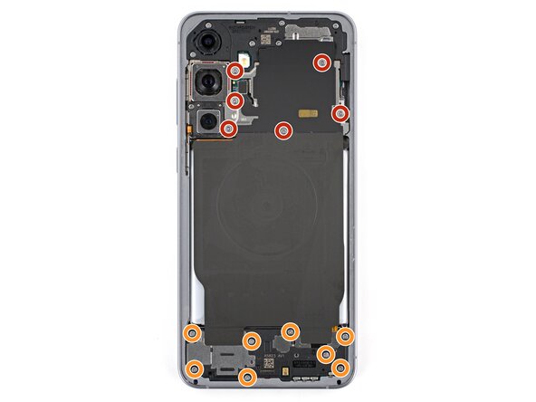
- Use a screwdriver to remove the fourteen screws securing the wireless charging and loudspeaker assembly:
- Six 3.5 mm‑long screws securing the wireless charging coil
- Eight 3.5 mm‑long screws securing the loudspeaker
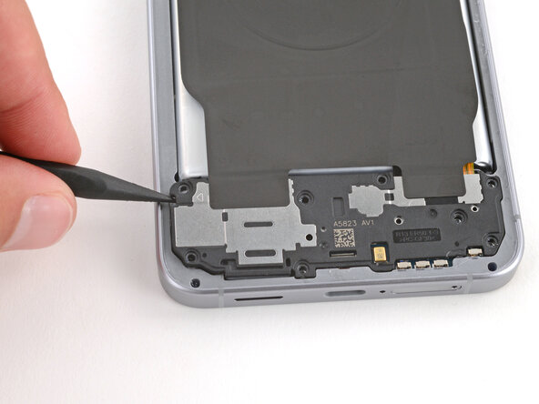
- Use the point of a spudger to pry up and lift the left side of the loudspeaker to unclip it.
- During reassembly, press firmly around the perimeter of the loudspeaker to engage its clips.
- Use two hands to remove the wireless charging and loudspeaker assembly.
- Every press connector has a corresponding gold arrow on the board that shows the proper location to pry—nifty! Prying at the wrong location risks damaging the fragile surface‑mounted components on the board.
- Use the point of a spudger to pry up and disconnect the battery press connector.
- Firmly press a SIM eject tool, bit, or straightened paper clip into the SIM card tray hole on the bottom edge of your phone until the tray ejects.
- A small mic hole is next to the SIM tray—don't confuse the two!
- Remove the SIM card tray.
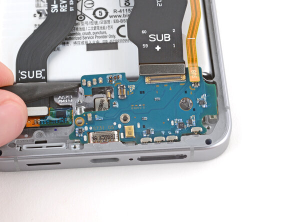
- Use the point of a spudger to pry up and disconnect the three press connectors from the top edge of the USB-C board (two interconnect cables and the fingerprint reader).
- Optionally, you can disconnect the other ends of the two interconnect cables from the motherboard and remove them for better access.
- During reassembly, remember to reconnect both ends of the interconnect cables if you removed them.
- Use a Phillips screwdriver to remove the two 3.5 mm‑long screws securing the USB-C board.
- Gently lift the fingerprint cable out of the way of the USB-C board.
- Before trying to remove the board, make sure you've removed the SIM card tray.
- Use the point of a spudger to pry up and unclip the top corners of the USB-C board.
- Don't pry against the battery—if damaged, it's a safety hazard.
- During reassembly, press down firmly on the center of the board to clip it into place.
- Be careful not to press on any small, surface‑mounted components.
- Pull the USB-C board towards the top of the phone and remove it.
- During reassembly:
- Make sure all three cables that connect to the USB‑C board are out of the way—you may need to hold them up as you insert the board.
- Insert the USB‑C board at a slight downward angle, guiding the port into its recess. Make sure the push connectors on the bottom edge are properly seated against the frame.