iPhone 17 Pro Max USB-C Port Assembly Replacement
ID: 206397
Description: Follow this guide to remove and replace the...
Steps:
- Let your iPhone's battery drain below 25% before starting this repair—a charged lithium‑ion battery may catch fire if damaged.
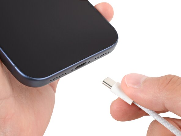
- Unplug all cables from your phone.
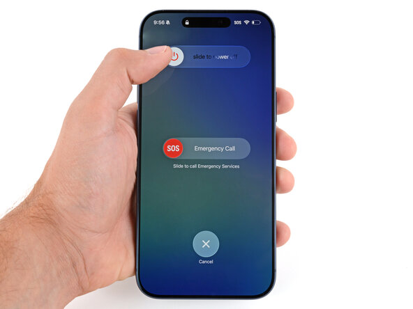
- Hold the power and either volume button and slide to power off your phone.
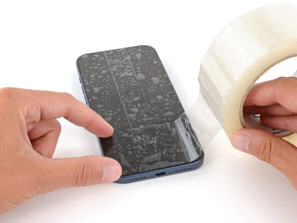
- Glass shards can complicate disassembly—or worse, cause injury. If your phone is cracked, follow this step.
- Apply strips of packing tape to the cracked glass until it's completely covered—this will help keep the glass contained and allow the suction cup to stick.
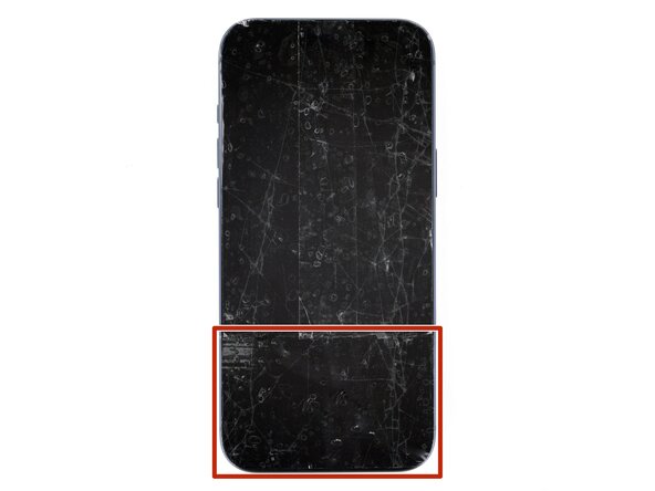
- Make sure there's a single strip of tape (not overlapping) across the bottom edge, big enough for a suction cup to fit on.
- Only cover the glass itself—don't stick any tape to the frame.
- Consider wearing safety glasses to protect your eyes from any glass shaken free during the repair.
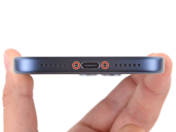
- Use a P2 pentalobe screwdriver to remove the two 7.5 mm‑long screws on either side of the charging port.
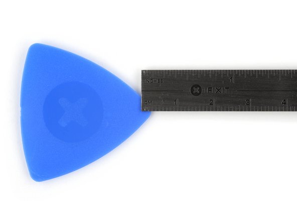
- If inserted too far, an opening pick can damage your device. Follow this step to mark your pick and prevent damage.
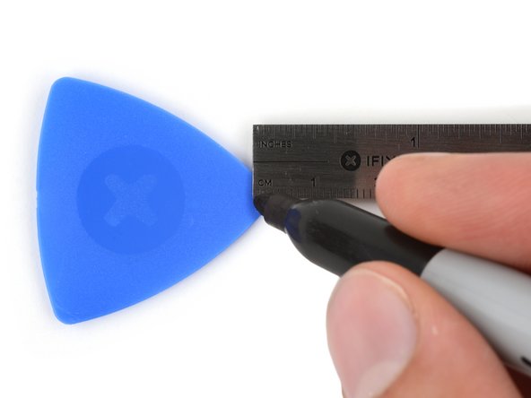
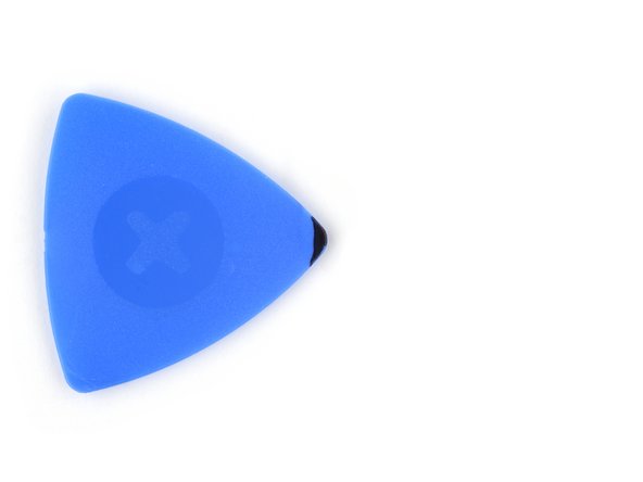
- Measure 3 mm from the tip and mark the opening pick with a permanent marker.
- Alternatively, you can tape a coin 3 mm from the tip of the pick.
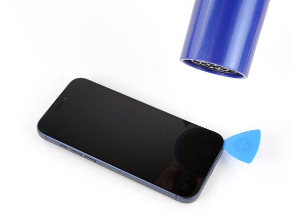
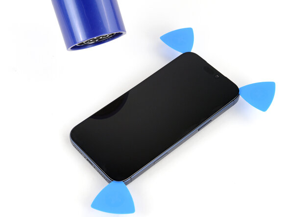
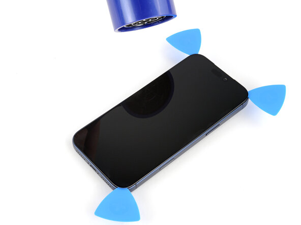
- Use a hair dryer or heat gun to heat the bottom edge of the screen until it's slightly too hot to touch.
- Improper use of a heat gun can destroy the display and/or battery—follow the linked instructions carefully.
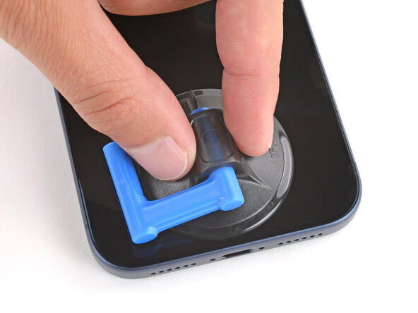
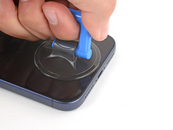
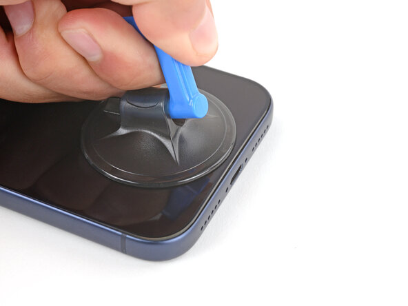
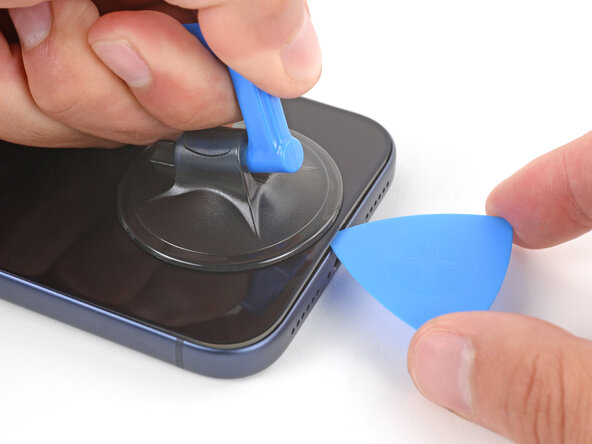
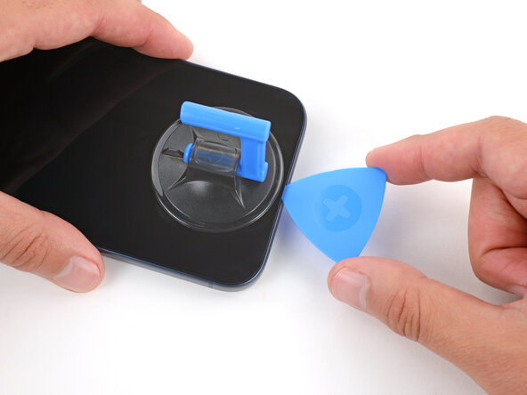
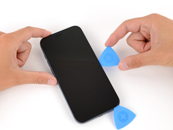
- Apply a suction handle to the bottom edge of the screen, as close to the edge as possible.
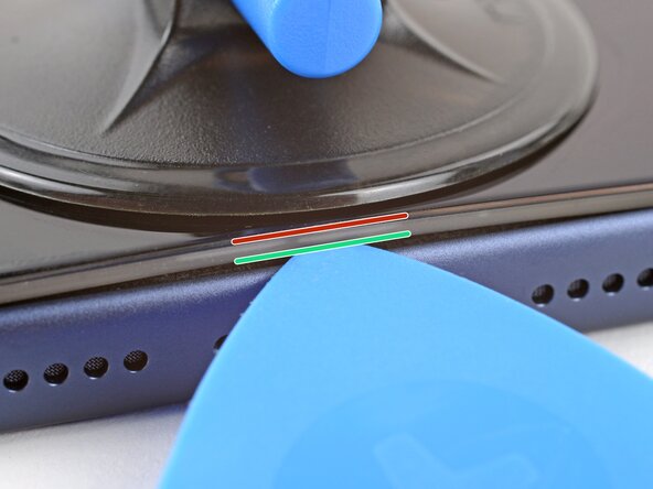
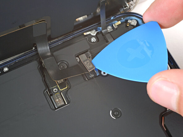
- During the next step, make sure you're inserting your pick in the correct location:
- There's a plastic bezel on the underside of the screen that sits on the frame. Insert your pick here, making sure it's completely under the bezel.
- There's a seam between the plastic bezel and the display panel. Don't insert your pick here or you'll separate the two, complicating the repair.
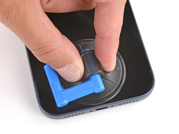
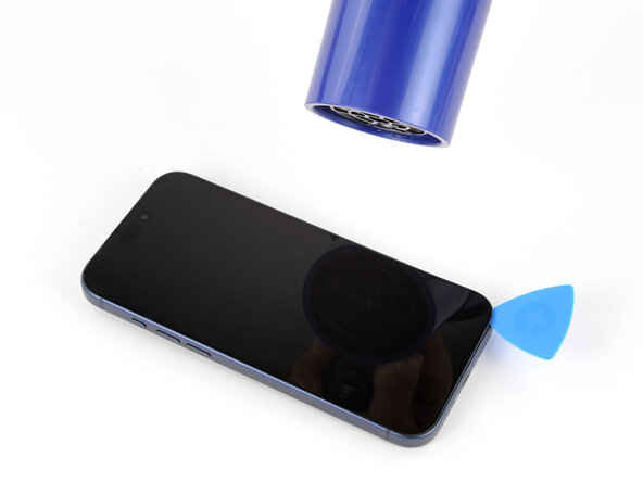
- Pull up on the suction handle with strong, steady force until a gap forms between the screen and frame.
- This may take significant force. If you're having trouble, reheat the screen and try again.
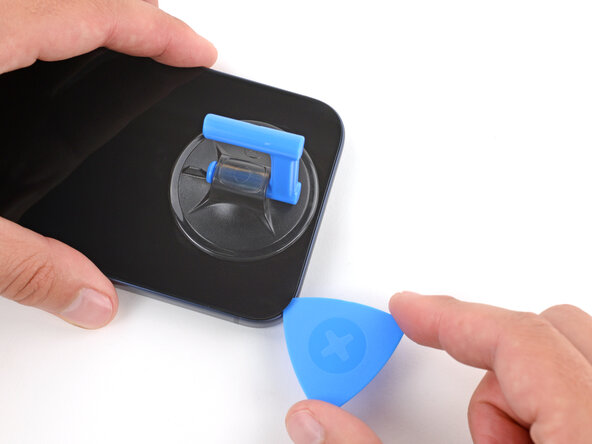
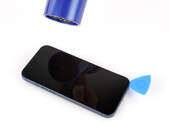
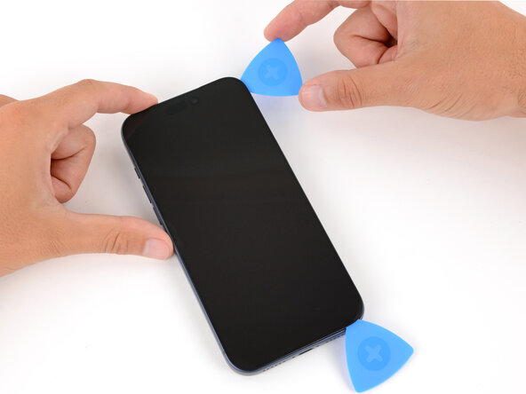
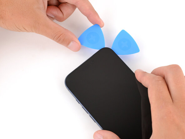
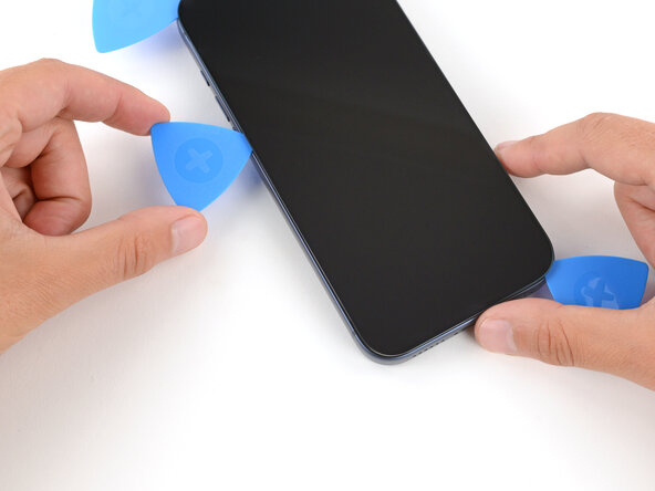
- Insert the tip of an opening pick in the gap you just created.
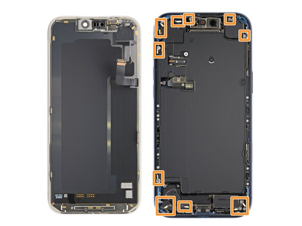
- Don't insert your pick more than 3 mm under the screen to avoid damaging the following components:
- The screen and ambient light sensor cables are located near the volume and Action buttons.
- There are delicate spring contacts around the perimeter of the phone.
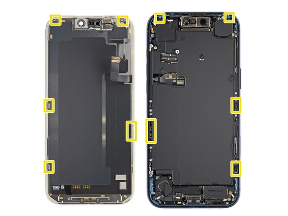
- The underside of the screen has thin, metal clips that go into corresponding slots on the frame.
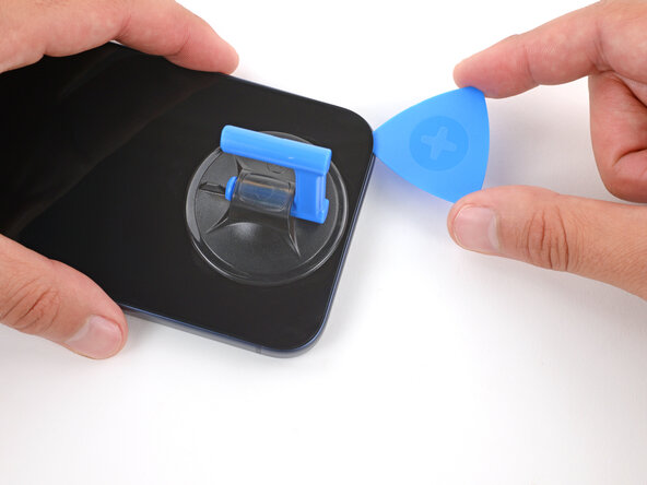
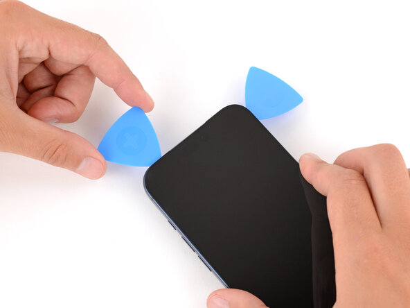
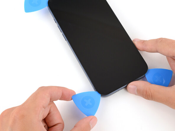
- Slide the opening pick along the bottom edge to separate the adhesive.
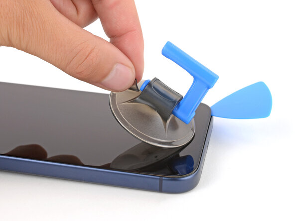
- Leave the pick inserted under the bottom right corner to prevent the adhesive from re‑sealing.
- Pull the small nub on the suction cup to remove it from the screen.
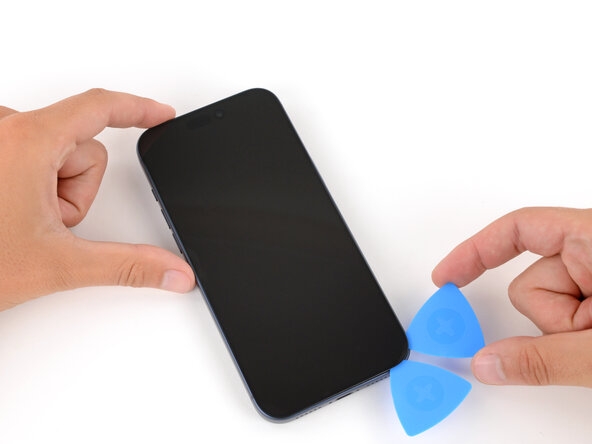
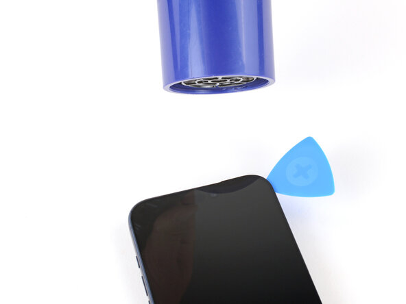
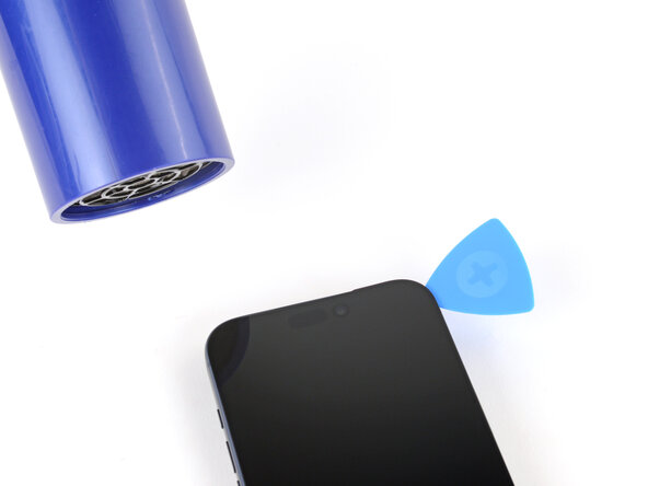
- Use a hair dryer or heat gun to heat the right edge of the screen until it's slightly too hot to touch.
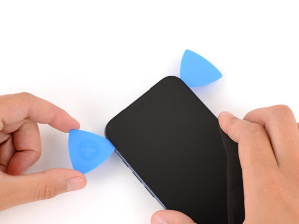
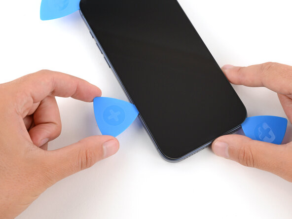
- Insert a second opening pick under the bottom right corner of the screen.
- Slide the pick up the right edge to separate the adhesive and release the two clips.
- You may need to pry the screen up slightly to release the clips
- Leave the pick inserted under the top right corner to prevent the adhesive from re‑sealing.
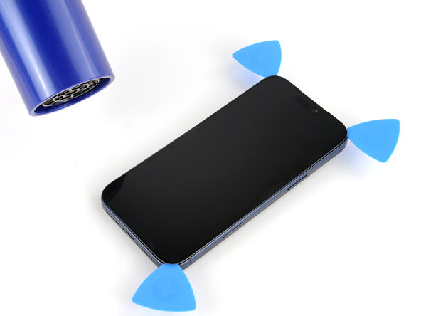
- Use a hair dryer or heat gun to heat the top edge of the screen until it's slightly too hot to touch.
- Insert a third opening pick under the top right corner of the screen.
- Slide the pick along the top edge and barely around the top left corner to separate the adhesive and release the two clips.
- Don't slide the pick farther, or you may damage the ambient light sensor cable.
- Leave the pick inserted under the top left corner to prevent the adhesive from re‑sealing.
- Use a hair dryer or heat gun to heat the left edge of the screen until it's slightly too hot to touch.
- Insert a fourth opening pick under the bottom left corner of the screen.
- Slide the pick up the left edge to separate the adhesive and release the clip, stopping just before the volume up button.
- You may need to pry up the screen slightly to release the clip.
- Don't slide the pick farther, or you may damage the screen cable.
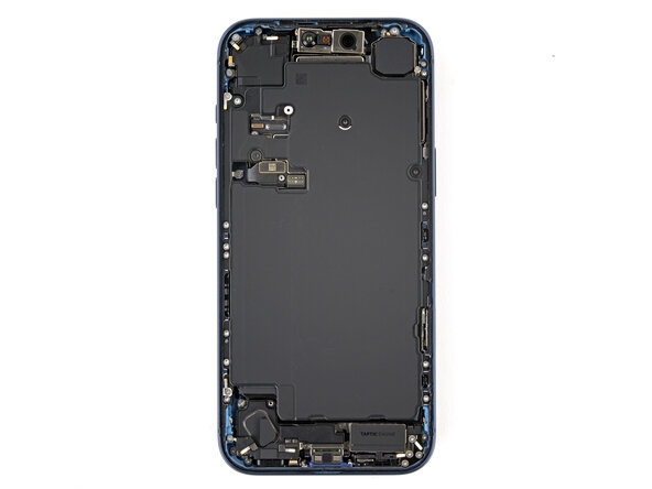
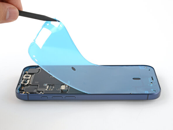
- At this point, the screen should be completely detached from the frame. If it feels stuck, go back around the perimeter and separate any remaining adhesive or clips.
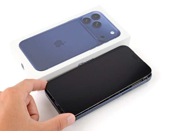
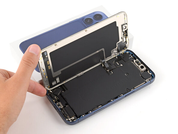
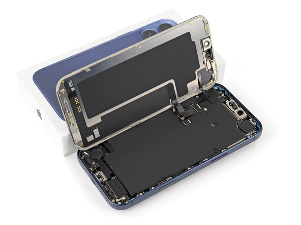
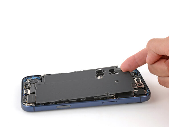
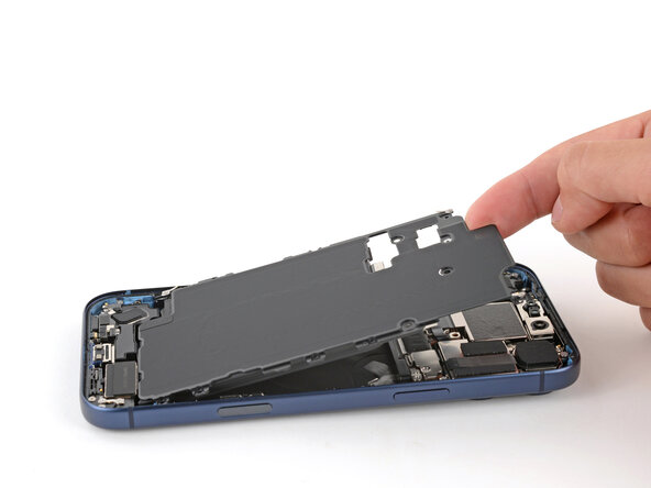
- Lift the screen straight up and swing it over the left edge, propping it up against a sturdy box or stack of books so the cables aren't strained.
- Alternatively, you can lay the screen down flat over the left side.
- Throughout this repair, keep track of each screw and make sure it goes back exactly where it came from.
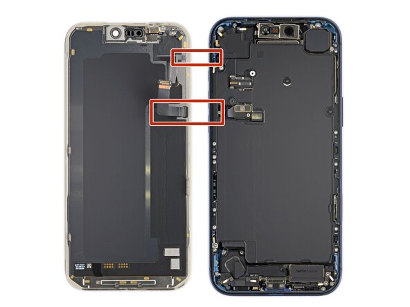
- Use a JIS 00 screwdriver to remove the two 1.2 mm‑long screws securing the battery and screen cable covers (one for each cover).
- Small iFixit Phillips bits are designed to work with JIS screws. You can try Phillips screwdrivers from other manufacturers, but you risk stripping the screw.
- Remove the two covers.
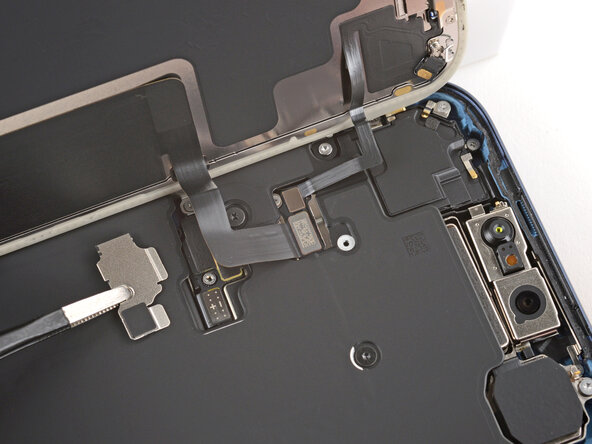
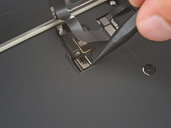
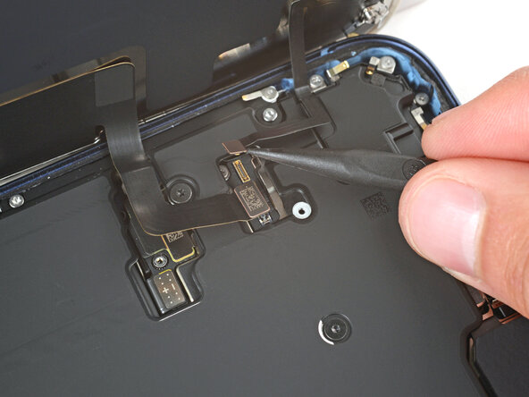
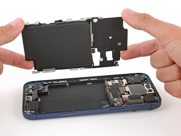
- Use the point of a spudger to pry up and disconnect the battery press connector.
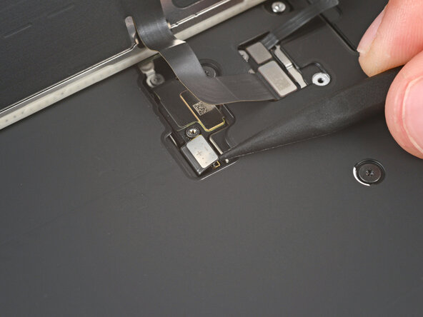
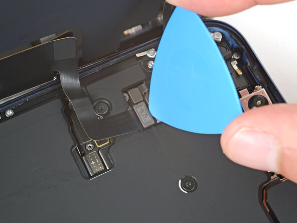
- Use the tip of an opening pick or the point of a spudger to pry up and disconnect the screen and front sensors press connectors.
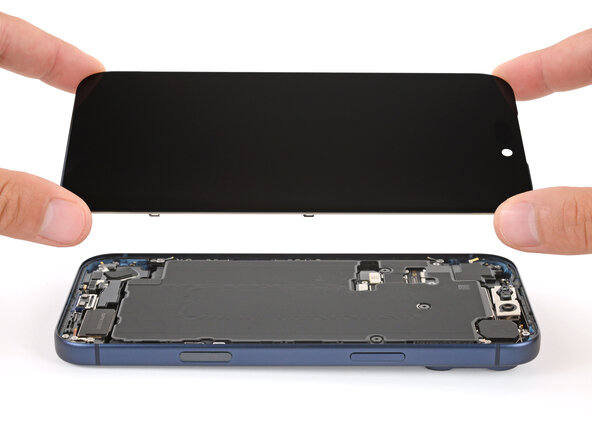
- Remove the screen.
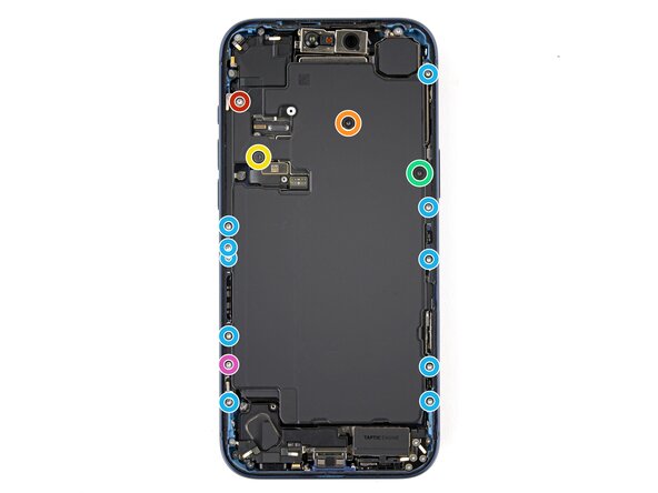
- Use a Torx Plus 4IP screwdriver to remove the screws securing the battery tray:
- One 7.5 mm‑long screw
- One 5.9 mm‑long screw
- One 3.5 mm‑long screw
- One 2.4 mm‑long screw
- Ten 3.7 mm‑long screws
- One 3.7 mm‑long screw
- iPhone models with a physical SIM card won't have this screw.
- Use your finger to lift the top left corner of the battery tray and remove it.
- Be careful not to smudge the front camera.
- Slide the tip of an opening pick along the top edge of the Taptic Engine to separate the plastic buffer strip adhered to it.
- Use a JIS 00 screwdriver to remove the six screws securing the loudspeaker:
- Two 2.7 mm‑long screws
- Two 2.0 mm‑long screws
- One 1.5 mm‑long screw
- One 1.5 mm‑long screw attached to the bottom edge
- An adhesive gasket holds the loudspeaker to the frame.
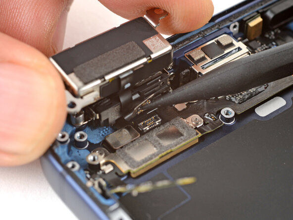
- Tilt the top edge of the loudspeaker out of its recess.
- Slowly pull the loudspeaker away from the frame to release the adhesive.
- Remove the loudspeaker.
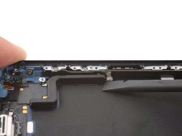
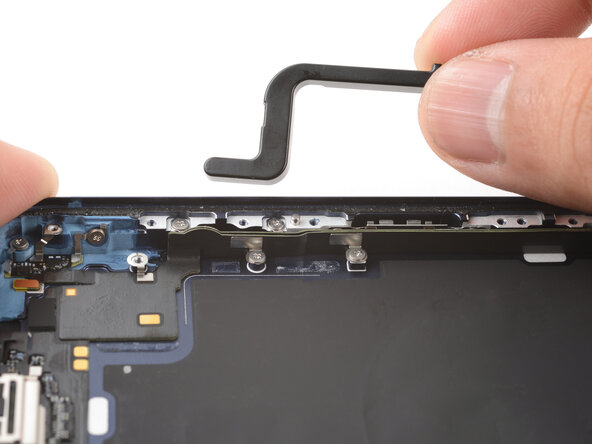
- Use a JIS 00 screwdriver to remove the two 1.9 mm‑long screws securing the ground clip.
- Use tweezers to remove the ground clip.
- The clip is delicate and easy to lose. Store it in a safe place for reassembly.
- Use a JIS 00 screwdriver to remove the three screws securing the flex antenna:
- One 1.7 mm‑long screw
- Two 1.9 mm‑long screws
- Use your fingers or a spudger to swing the flex antenna out of the way to access the screws beneath it.
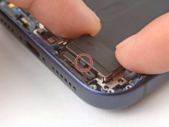
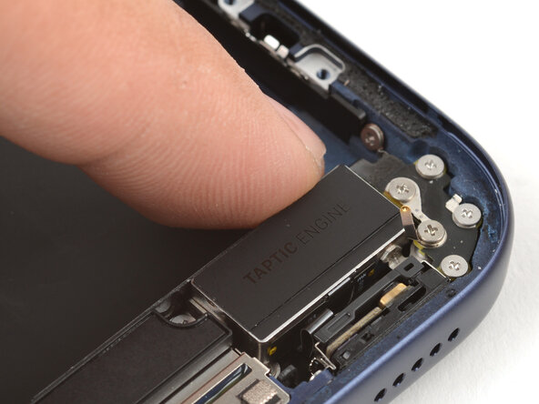
- Use a standoff screwdriver to remove the two 4.0 mm‑long screws securing the Taptic Engine.
- Use your fingers to flip the Taptic Engine out of its recess and onto the edge of the iPhone.
- Hold onto the Taptic Engine during the next step to prevent straining its cable.
- Use the point of a spudger to pry up the Taptic Engine press connector and disconnect it.
- Remove the Taptic Engine.
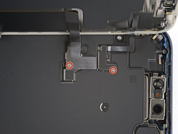
- Use the point of a spudger to pry up and disconnect the lower microphone connector.
- Remove the two screws securing the lower microphone:
- One 3.2 mm-long standoff screw
- One 3.1 mm-long JIS 00 screw attached to the bottom edge of the iPhone frame
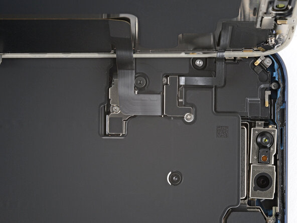
- The lower microphone is still attached to the frame by an adhesive gasket.
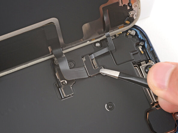
- Use a hair dryer or an iOpener to heat the bottom-right corner of the iPhone until it's warm to the touch.
- Insert the point of an opening pick between the lower microphone and the frame.
- Slide the pick along the edge to create a gap between the microphone and the frame.
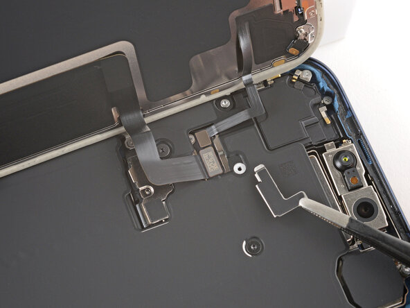
- Insert the flat edge of a spudger into the gap between the lower microphone and the frame.
- Twist the spudger slowly to pry the microphone off the frame.
- Remove the lower microphone.
- Use a hair dryer or an iOpener to heat the black plastic battery buffer until it's warm to the touch.
- The large black graphite sheet (which looks like a black sticker) inside the frame is delicate. Be mindful not to scrape it with your spudger.
- If you nick the graphite sheet, don't worry—it'll still function normally.
- Use the flat end of your spudger to pry up one end of the battery buffer.
- Grab the buffer with your fingers and slowly lift and remove it.
- Use the point of a spudger to pry up and disconnect the two USB-C press connectors (one's underneath the other) from the bottom-left corner of the logic board.
- Use a JIS 00 screwdriver to remove the two 1.8 mm‑long screws securing the left logic board buffer.
- Remove the left logic board buffer and store it for reassembly.
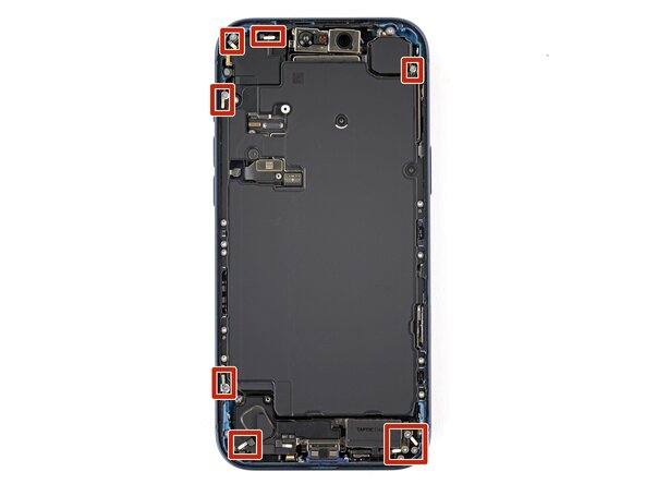
- Remove the nine screws securing the USB-C port assembly:
- Six 1.5 mm‑long JIS 00 screws
- One 1.3 mm‑long JIS 00 screw
- Two 1.2 mm‑long Y000 screws
- If your iPhone doesn't have mmWave functionality, you may not have these screws.
- Use a JIS 00 screwdriver to remove the 1.2 mm‑long screw securing the USB-C port assembly to the bottom left corner of the frame.
- Use a JIS 00 screwdriver to remove the two 2.8 mm‑long screws securing the USB-C port to the bottom edge of the frame.
- Use the point of a spudger to pry and separate the buffer strip covering the screw in the bottom right corner of the frame.
- Use a JIS 00 screwdriver to remove the 1.2 mm‑long screw securing the USB-C port assembly to the right edge of the frame.
- Use a hair dryer or an iOpener to heat the entire USB-C port assembly until it's warm to the touch.
- Slide the point of an opening pick between the microphone module (left of the USB-C port) and the bottom edge of the frame.
- Pry gently to separate the microphone from the frame.
- The large black graphite sheet inside the frame is delicate. Be very mindful not to tear it with your opening pick.
- Slide the opening pick under the USB-C port assembly, near the center.
- Slide the pick towards the right edge of the frame to separate the adhesive holding the assembly.
- Grab the USB-C port assembly with your fingers and slowly pull it away from the frame to remove it.
- If the USB-C port assembly feels stuck, check for any missed screws and separate any remaining adhesive.
- Congratulations on completing disassembly! The remaining steps will show how to reassemble your iPhone.
- Depending on your iPhone model, some reassembly photos may have minor visual discrepancies. The procedure, however, will be correct for your iPhone.
- Carefully inspect your replacement USB-C port assembly and remove any adhesive liners.
- Align the assembly with the bottom edge of the frame and place it loosely in place.
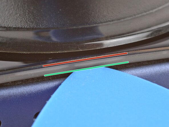
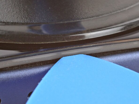
- Use a JIS 00 screwdriver to install the two 2.8 mm‑long USB-C port screws to the bottom edge of the frame.
- Make sure to install these screws in the holes marked in green, not red.
- Install the nine USB-C port assembly screws:
- Six 1.5 mm‑long JIS 00 screws
- One 1.3 mm‑long JIS 00 screw
- Two 1.2 mm‑long Y000 screws
- Use a JIS 00 screwdriver to install the 1.2 mm‑long USB-C port assembly screw to the bottom left corner of the frame.
- Use a JIS 00 screwdriver to install the 1.2 mm‑long USB-C port assembly screw to the right edge of the frame.
- Use a spudger or your finger to press the buffer strip back onto the frame. It should cover the screw you just installed.
- Use tweezers to remove the adhesive from where the microphone attaches to the frame.
- If the adhesive gasket isn't deformed and your replacement USB-C port assembly didn't come with adhesive, you can reuse the existing gasket. Be aware that you'll lose water and dust resistance.
- You can use some double-sided tape as a replacement adhesive. Use a pin to poke a hole through the tape. Enlarge it enough for the mic hole, then apply the tape to the microphone.
- Use your finger to align and press the microphone module onto the frame.
- Use a hair dryer or an iOpener to heat the entire USB-C port assembly until it's warm to the touch. This helps the adhesive to bond better.
- Use your finger to press and connect the two press connectors to the logic board.
- Place the left logic board buffer in its recess.
- Use a JIS 00 screwdriver to install the two 1.8 mm‑long left logic buffer screws.
- Inspect the existing battery buffer adhesives on the frame. If they're still tacky and not deformed, you can reuse them.
- To replace the adhesives:
- Use a spudger and tweezers to remove the adhesives. Be careful not to scrape the delicate graphite sheet.
- Replace the adhesives with some double-sided tape.
- Use the first image to help align the battery buffer in the frame. It rests against (but doesn't cover) the thin white frame markings.
- Use your fingers to lay the battery buffer in place.
- Press down on the buffer for a few seconds to secure it.
- Use a hair dryer or an iOpener to heat the battery buffer until it's warm to the touch. This helps improve the adhesive bond.
- If the adhesive gasket isn't deformed and your lower microphone didn't come with a replacement gasket, you can keep and reuse the gasket. Be aware that you'll lose water and dust resistance.
- Use tweezers to remove the microphone adhesive gasket from the frame.
- If your replacement lower microphone comes with an adhesive gasket pre-installed, make sure to remove any liners to expose the adhesive.
- Use tweezers to align the microphone with the frame.
- Slide the microphone into its recess and press it in place. There should be almost no gap between the microphone and the frame.
- Use a hair dryer or an iOpener to heat the lower microphone until it's warm to the touch. This helps strengthen the adhesive bond.
- Install the two lower microphone screws:
- One 3.2 mm-long standoff screw
- One 3.1 mm-long JIS 00 screw attached to the bottom edge of the iPhone frame
- Use your finger to press and connect the lower microphone press connector.
- Place the Taptic Engine upside down on the edge of the iPhone frame.
- While holding the Taptic Engine with one hand, use your finger to press and connect the Taptic Engine press connector.
- Flip the Taptic Engine over the frame and align it using its screw holes.
- The Taptic Engine flex cable should fold neatly between the Taptic Engine and the frame.
- Use a standoff screwdriver to install the two 4.0 mm‑long Taptic Engine screws.
- Use your fingers or a spudger to fold the flex antenna down in place.
- Use a JIS 00 screwdriver to install the three flex antenna screws:
- One 1.7 mm‑long screw
- Two 1.9 mm‑long screws
- Use tweezers to carefully place the ground clip in place.
- Be sure to orient this clip correctly as shown in the images.
- Use a JIS 00 screwdriver to install the two 1.9 mm‑long ground clip screws.
- Align the bottom edge of the loudspeaker with the frame and lay it in its recess..
- Make sure the bottom-right screw tab seats properly against the frame. Gently bend it if it's out of place.
- Use your finger to press down on the loudspeaker until it clicks in place.
- Use a JIS 00 screwdriver to install the six loudspeaker screws:
- Two 2.7 mm‑long screws
- Two 2.0 mm‑long screws
- One 1.5 mm‑long screw
- One 1.5 mm‑long screw attached to the bottom edge of the iPhone frame
- Use your fingers or a spudger to press the buffer strip back onto the top edge of the Taptic Engine.
- Lay the battery tray in place.
- Make sure not to trap any cables underneath the tray.
- Use a Torx Plus 4IP screwdriver to install the battery tray screws:
- One 7.5 mm‑long screw
- One 5.9 mm‑long screw
- One 3.5 mm‑long screw
- One 2.4 mm‑long screw
- Ten 3.7 mm‑long screws
- One 3.7 mm‑long screw
- iPhone models with a physical SIM card won't have this screw.
- Work around the fragile grounding clips as you clean the frame. If you bend one out of place, gently bend it back with your fingers or tweezers.
- Use tweezers or your fingers to remove large pieces of adhesive from the frame perimeter.
- Use a spudger to scrape the adhesive residue off the frame.
- If the adhesive feels stubborn, apply some heat using a hair dryer or heat gun and try again.
- Apply a few drops of high concentration (>90%) isopropyl alcohol to the adhesive residue.
- Use a microfiber or lint-free cloth to wipe in one direction along the perimeter of the frame to clean the residue.
- Take your time doing this. A clean frame allows replacement adhesive to lay evenly, ensuring a better bond.
- If you're reusing your screen, apply a few drops of highly-concentrated isopropyl alcohol (over 90%) to a microfiber or lint-free cloth and wipe around the perimeter to prepare the surface for new adhesive.
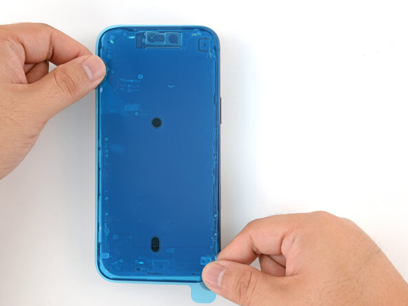
- Without peeling any liners, lay the adhesive sheet over the frame to determine its proper orientation.
- Use features such as the camera cutout and notches along the top and bottom edges to visualize how the adhesive will lay in the frame.
- Grab the tab in the corner of the adhesive sheet and peel the liner to expose a third of the adhesive.
- The exposed adhesive is very sticky. Don't let it touch anything until you're ready to apply it to the frame.
- If your adhesive has multiple liners, peel the liner that exposes the side that sticks to the frame.
- Once the adhesive is pressed into place, you can't reposition it—you'll have to remove it and start over with new adhesive.
- Carefully align the exposed edge of the adhesive strip with the corresponding edge of the iPhone's frame.
- When it's correctly aligned, gently press the exposed adhesive strip onto the frame.
- Continue peeling away the liner from the adhesive as you gently press the adhesive into place.
- If you've correctly aligned the adhesive, the edges will fall perfectly into place.
- If your adhesive is slightly misaligned, gently pull the long edges into alignment with the frame.
- If the adhesive begins to crease or wrinkle, remove it and start over with fresh adhesive.
- If you don't have another set of adhesive strips handy, it's okay to temporarily put your iPhone back together and use it normally without any adhesive. Just keep in mind that your iPhone's water resistance will be compromised until you replace the adhesive.
- Use a spudger to press the adhesive around the entire perimeter of your iPhone.
- Work around the fragile grounding clips. If you bend one out of place, gently bend it back with your fingers or tweezers.
- Use the pull tab to peel off the large front liner from the adhesive. The pull tab is often in a corner of the liner.
- At this point, you'll still have liners covering the perimeter. Don't remove these liners yet—they prevent the adhesive from accidentally sticking while you reassemble your iPhone.
- Set the iPhone screen next to the frame such that the screen cables can comfortably reach the logic board.
- Use your finger or the flat end of a spudger to press and connect the two screen connectors onto the logic board.
- Don't try to force the connector into place. If you're having trouble, reposition it and try again.
- Use your finger or the flat end of a spudger to press and connect the battery connector onto the logic board.
- This is a good point to test your repair before sealing up your iPhone:
- Power on your iPhone and make sure it works as expected. Power it back down and continue reassembly.
- If your iPhone doesn't turn on, connect it to a power source and try again.
- Tuck the top edge of the battery connector cover under the cutout lip.
- Make sure both tabs are tucked under the lip.
- Align the cover by its screw hole and lay it in place.
- Use a JIS 00 screwdriver to install the 1.2 mm‑long screw to secure the battery connector cover.
- Tuck the left edge of the screen connector cover under the cutout lip.
- Align the cover by its screw hole and lay it in place.
- Use a JIS 00 screwdriver to install the 1.2 mm‑long screw to secure the screen connector cover.
- With one hand hold the screen steady.
- Use your fingers or a spudger to peel away all perimeter liners, exposing the adhesive.
- Make sure nothing touches the exposed adhesive.
- Check the internals for any stray liners and remove them. There should be no liners remaining.
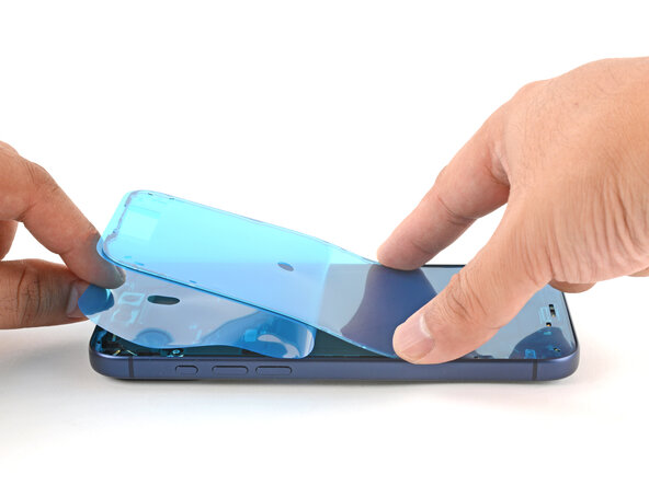
- Lower the screen onto the frame, beginning with the top edge.
- If you feel resistance, a perimeter clip may have bent out of place and is being crushed by the frame. Look at the point of resistance and gently straighten any bent clips.
- Make sure the screen edge isn't pinching any cables.
- Press along the edges of the iPhone until the screen sits flush against the frame.
- Firmly squeeze around the entire perimeter of the iPhone.
- Use a hair dryer, heat gun, or an iOpener to heat the screen perimeter until it's slightly too hot to touch.
- The heat softens the adhesive and helps create a better bond.
- Use a P2 pentalobe screwdriver to install the two 7.5 mm‑long screws on either side of the charging port.