Ubiquiti Unifi Entry Sensor | USL-Entry
ID: 211997
Description: Unifi Protect SuperLink sensor with up to...
Steps:
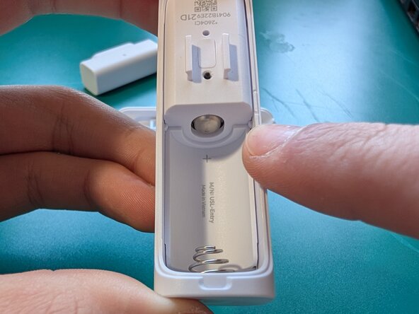
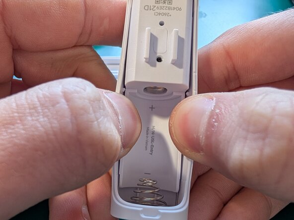
- Begin by removing the battery cover. Use the included tool to pop off the edge, then pry outwards to disconnect the large plastic clips that are further down.
- To remove the inner body from the outer shell, you will have to get it around both the battery connectors and the two plastic retaining clips at the center.
- You can pull on the outer walls to move the plastic clips out of the way, then push a metal pick behind the edge of the inner body by the battery holder.
- Depress the battery contact spring out of the way as you pry the inner body out. once you get the edge of the battery holder past the contact spring, it should lift out easily.
- The button face will fall out naturally as it is not held in with anything except the pressure of the button behind it
- The battery contact is held on with adhesive tape. I was not able to separate it from the shell with prying alone.
- I used a hot air rework station set to 300°F 149°C at max air speed. I heated the metal directly until it was heat-soaked, about 1 minute
- I used a sharp pair of tweezers in the corner to pry the contact off the back shell while it was still hot
- Make sure you don't pry hard enough to bend the metal
- The main body is now free from the outer chassis
- Unscrew the 2 Phillips #1 screws near the wireless antenna
- Scrape off any glue holding the top PCB near the battery contact
- Gently pull the top PCB directly upward to disconnect it from the connector on the bottom PCB
- Remove the 2 Phillips #0 screws near the battery connector. these screws are holding the PCB down, as well as holding the battery contacts against the board's power inputs
- A small adhesive-backed plastic cover wraps around the button on the end of the PCB, and covers the plastic welds of the LED light pipes to prevent light leaks. it sits under the rubber light pipe cover
- you can now gently remove the rubber light pipe cover to further expose the LEDs and their light pipes