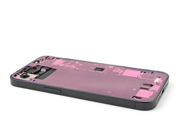
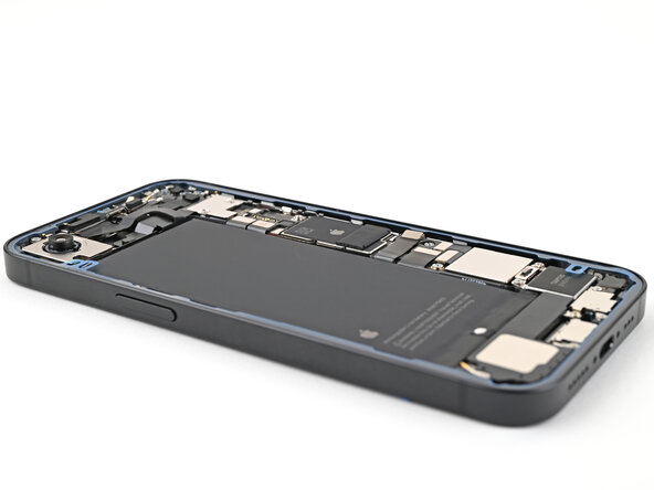
iPhone 17e Microphone Replacement
ID: 212445
Description: Use this guide to replace the microphone in an...
Steps:
- Allow your phone's battery to drain below 25%, as a charged lithium-ion battery is a potential safety hazard.
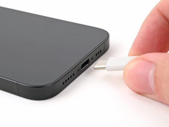
- Unplug any cables from your phone.
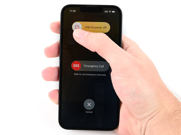
- Hold the power button and either volume button, then slide to power off your phone.
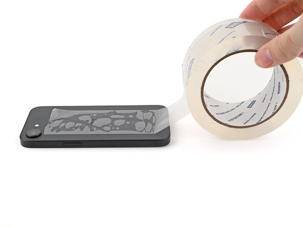
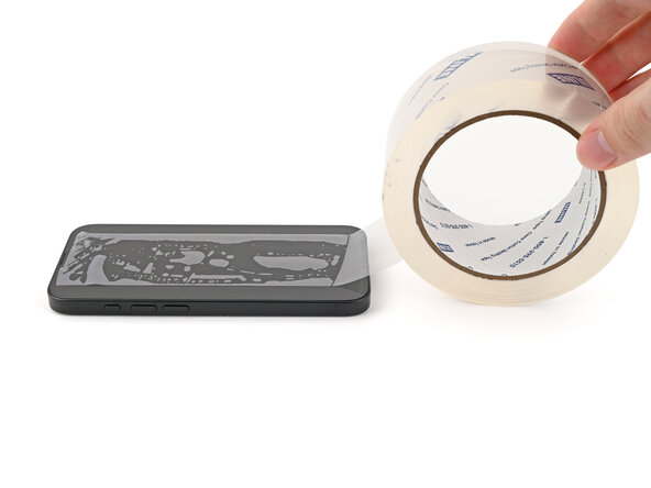
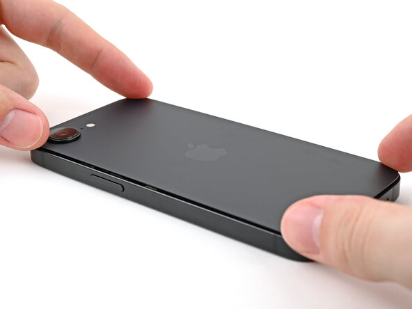
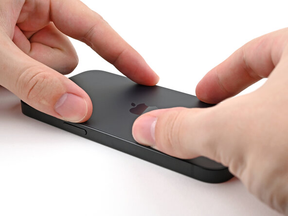
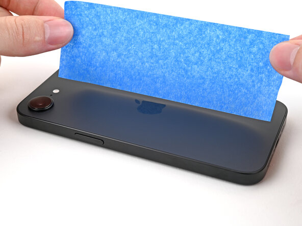
- If your screen or back glass is badly cracked, lay overlapping strips of packing tape over the glass to protect yourself and make disassembly easier.
- Make sure there's a smooth area near the bottom edge that's big enough for a suction cup to stick to.
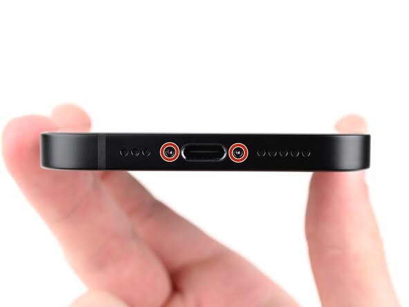
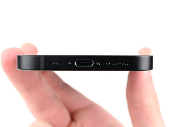
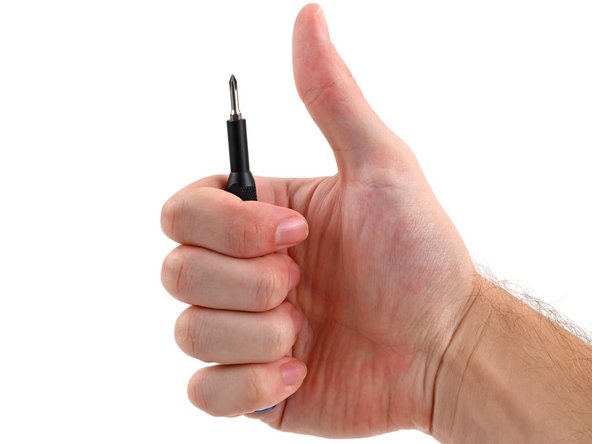
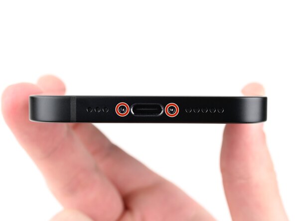
- Use a pentalobe P2 screwdriver to remove the two 7.8 mm‑long screws on either side of the charging port.
- If inserted too far, an opening pick can damage your device. Follow this step to mark your pick and prevent damage.
- Measure 3 mm from the tip and mark the opening pick with a permanent marker.
- You can also mark the other corners of the pick with different measurements.
- Alternatively, tape a coin to a pick 3 mm from the tip.
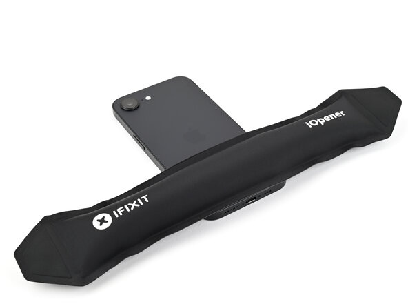
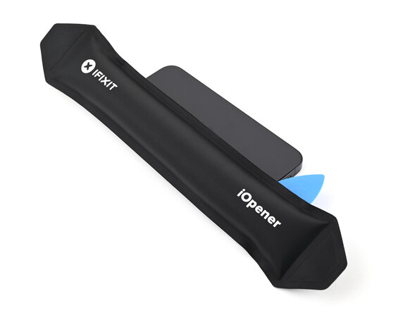
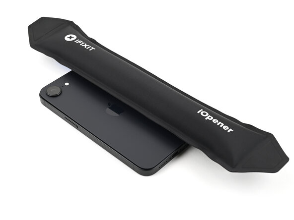
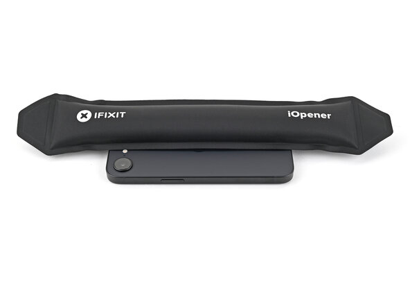
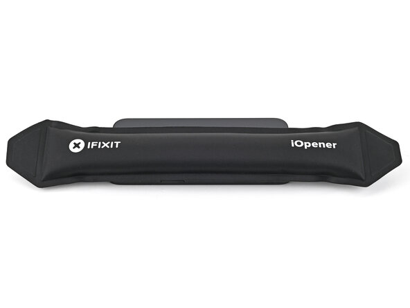
- Apply a heated iOpener to the bottom edge of the back glass for 90 seconds.
- Alternatively, you can use a hair dryer or heat gun to heat the bottom edge of the back glass until it's hot to the touch.
- Be careful not to heat the phone hotter than this—the battery is susceptible to heat damage.
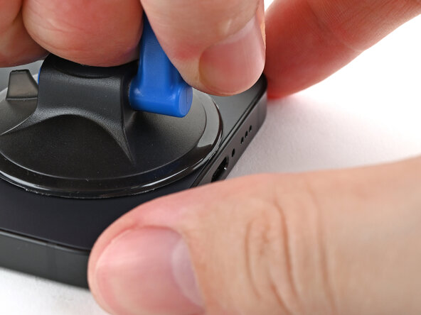
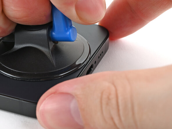
- Apply a suction handle to the bottom edge of the back glass.
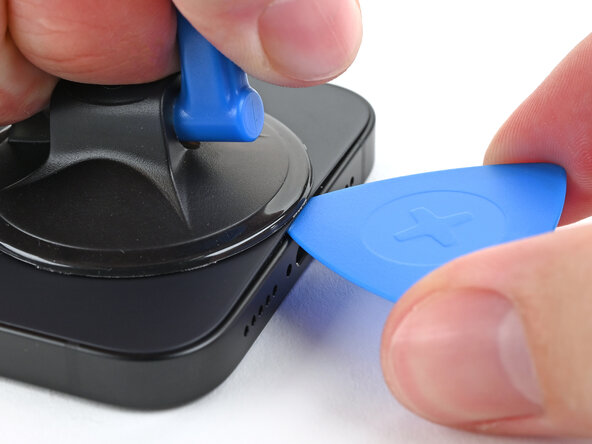
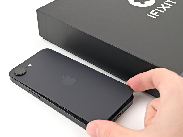
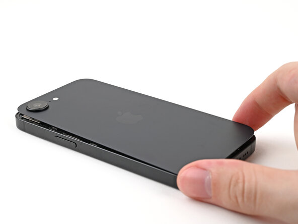
- Pull up on the handle with a strong, steady force to create a gap between the back glass and the frame.
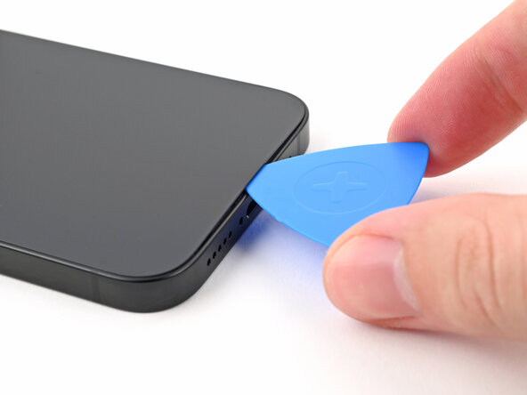
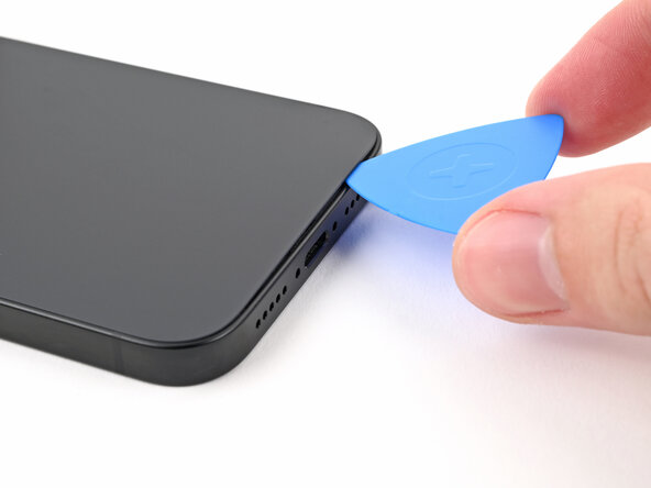
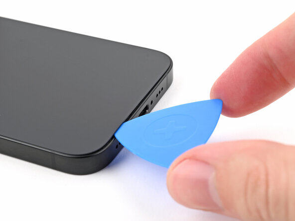
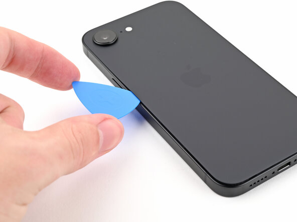
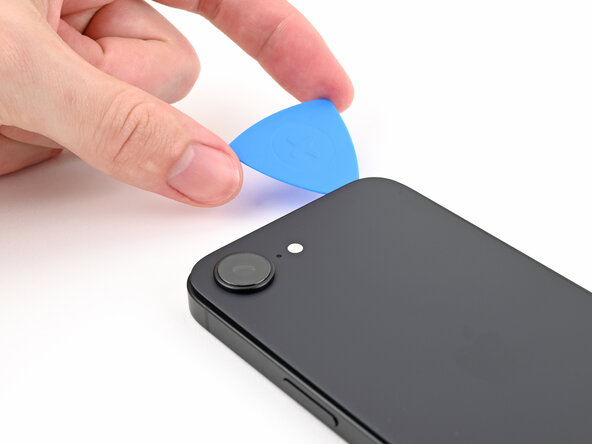
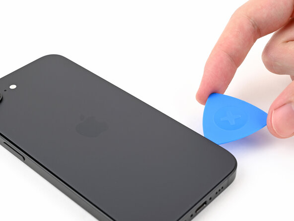
- Insert the tip of an opening pick into the gap.
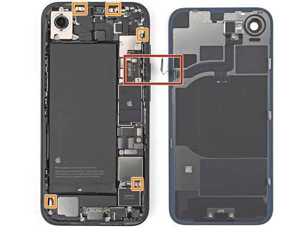
- As you slice the adhesive securing the back glass in the following steps, don't insert your pick deeper than 3 mm to avoid damaging the following areas:
- A delicate cable connecting the back glass to the phone, next to the volume up button.
- Multiple spring contacts around the perimeter of the phone.
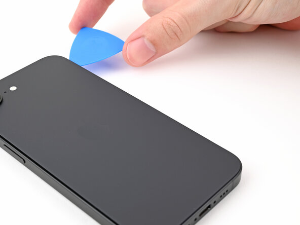
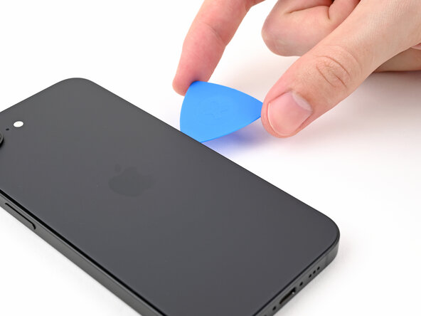
- Slide the opening pick along the bottom of the back glass to separate the adhesive.
- Leave the opening pick near the bottom left corner.
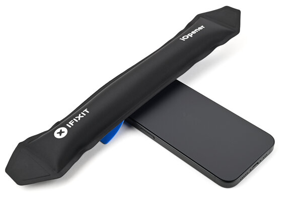
- Apply a heated iOpener to the left edge of the back glass for 90 seconds.
- When using a hair dryer or heat gun, heat the back glass until it's hot to the touch.
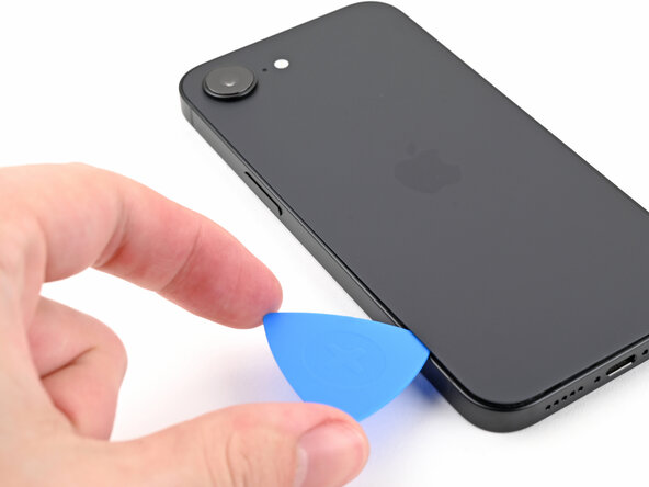
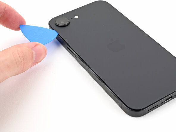
- Rotate the opening pick around the bottom left corner and slide it along the left edge to separate the adhesive and release the metal clips.
- You'll hear and feel the metal clips release as you pass them.
- Leave the opening pick near the top left corner.
- Apply a heated iOpener to the top edge of the back glass for 90 seconds.
- When using a hair dryer or heat gun, heat the back glass until it's hot to the touch.
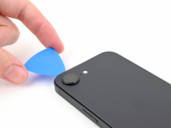
- Rotate the opening pick around the top left corner and slide it along the top edge to separate the adhesive and release the metal clips.
- You'll hear and feel the metal clips release as you pass them.
- Leave the opening pick in the top right corner.
- Apply a heated iOpener to the right edge of the back glass for 90 seconds.
- When using a hair dryer or heat gun, heat the back glass until it's hot to the touch.
- Don't insert your pick deeper than 3 mm to avoid damaging the hidden cable.
- Rotate the opening pick around the top right corner and slide it along the right edge to separate the remaining adhesive and the metal clip.
- You'll hear and feel the metal clip release as you pass it.
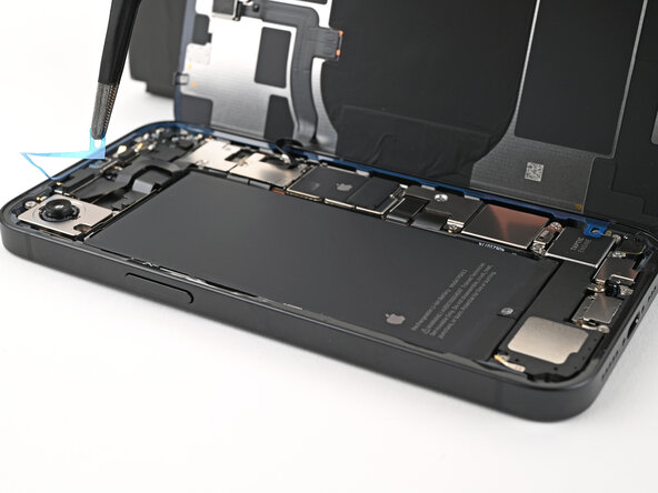
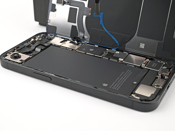
- Your back glass adhesive should now be completely separated. If it isn't, slide your opening pick around the back glass to separate any remaining adhesive.
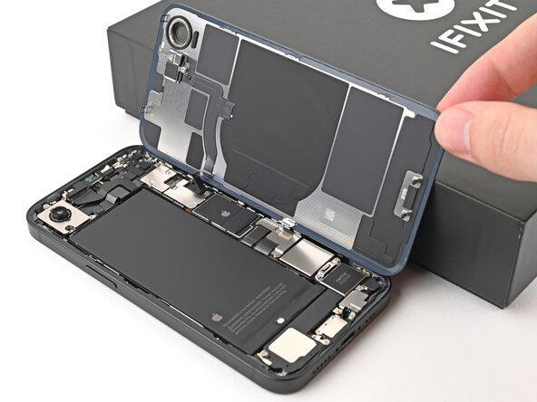
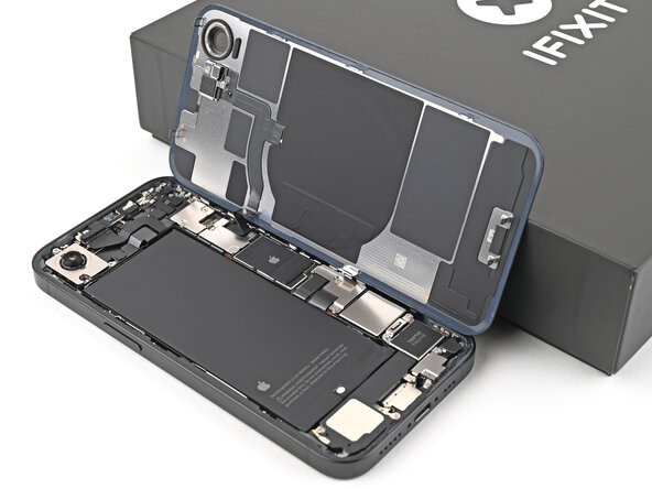
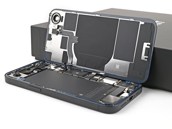
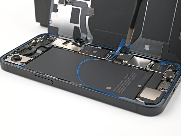
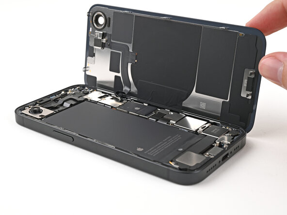
- Swing open the back glass to the right of the phone and support it upright on a clean, sturdy object.
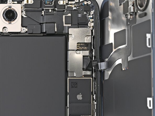
- Use a tri-point Y000 screwdriver to remove the two 1.3 mm‑long screws securing the lower connector cover.
- Use tweezers or your fingers to lift the lower connector cover and slide it toward the top of the phone to release it from its metal clip.
- Remove the lower connector cover.
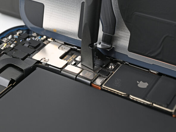
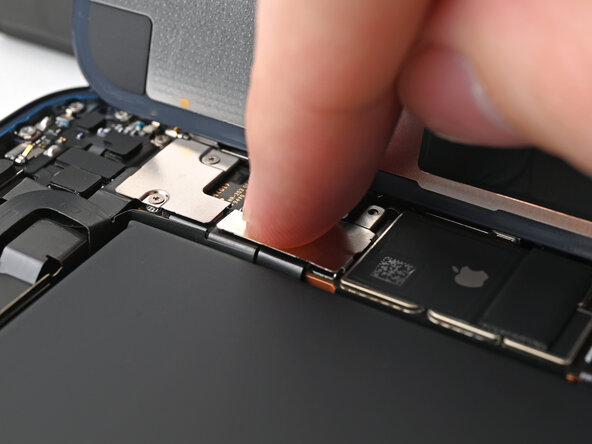
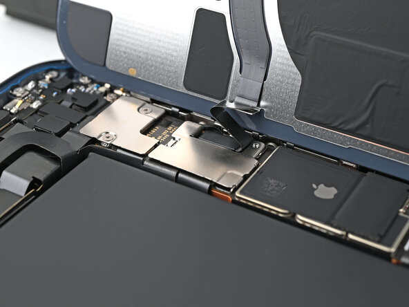
- Use the point of a spudger to pry up and disconnect the battery press connector.
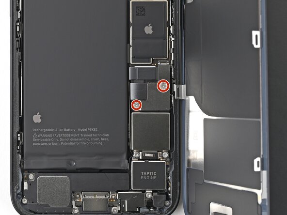
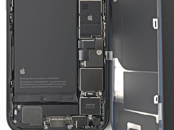
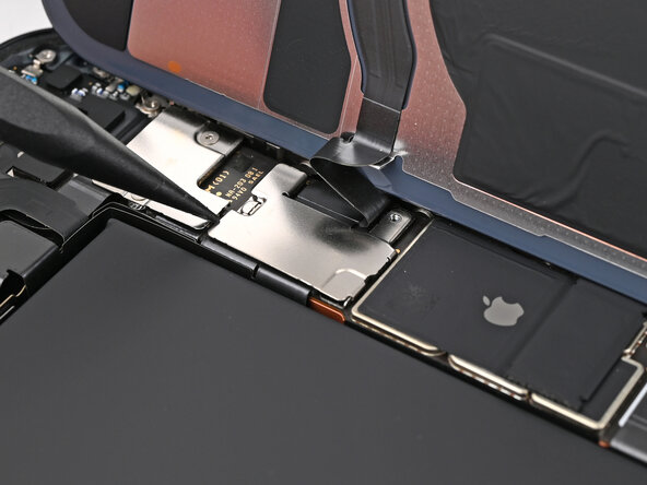
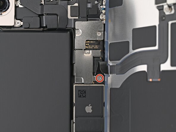
- Use a tri-point Y000 screwdriver to remove the 1.0 mm‑long screw securing the middle connector cover.
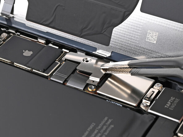
- The middle connector cover is slotted into two metal clips on the top and bottom.
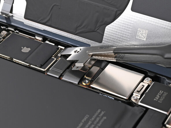
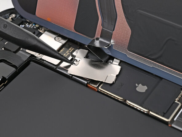
- Use the point of a spudger to push the middle connector cover towards the bottom of the phone to release its clips.
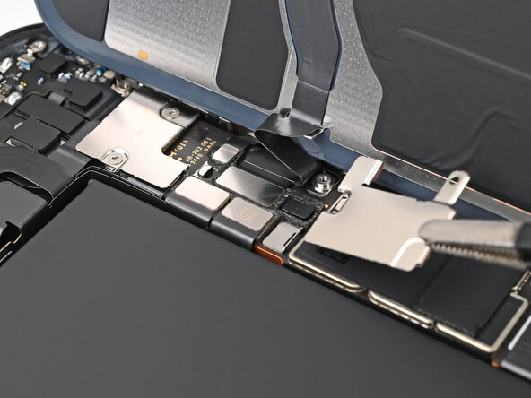
- Use tweezers or your fingers to remove the cover.
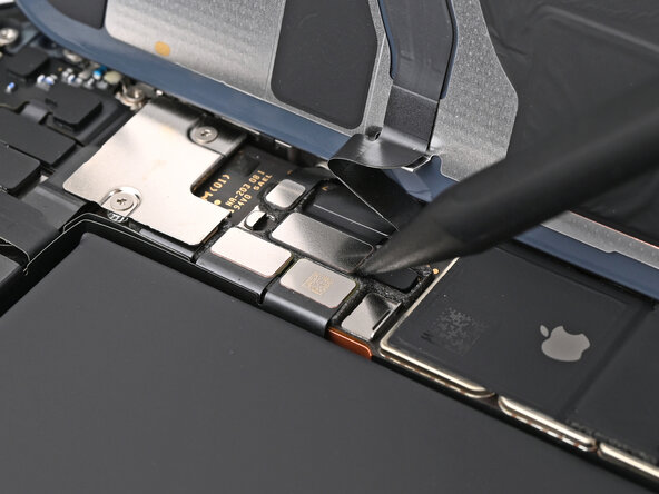
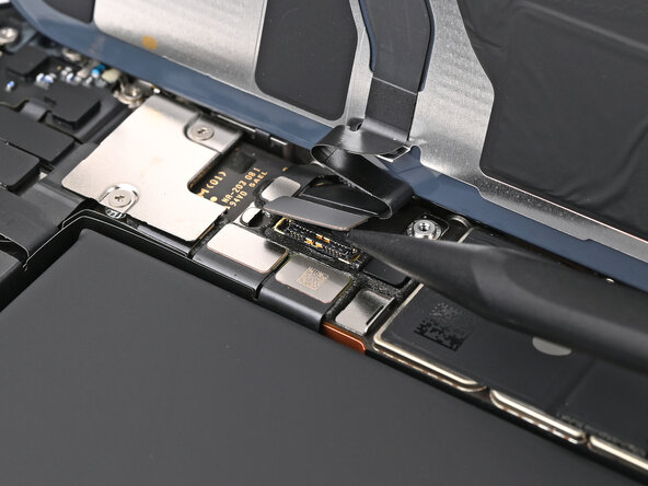
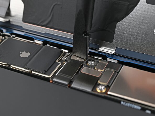
- Use the point of a spudger to pry up and disconnect the wireless charging coil press connector.
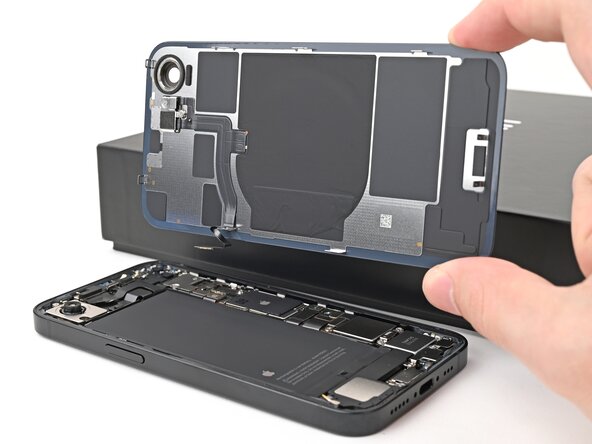
- Lift the back glass off the frame and remove it.
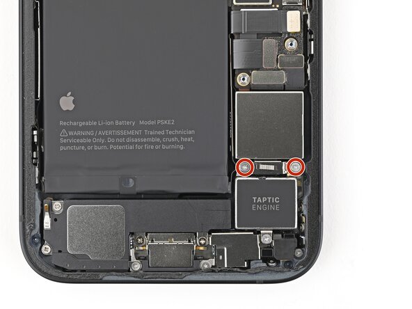
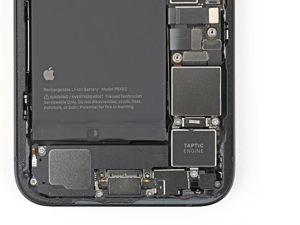
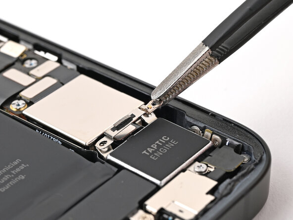
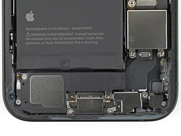
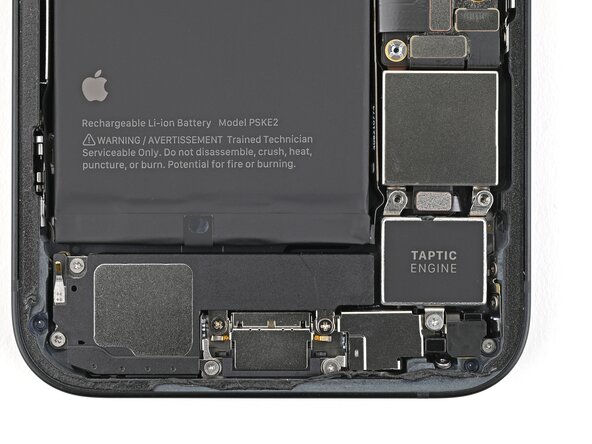
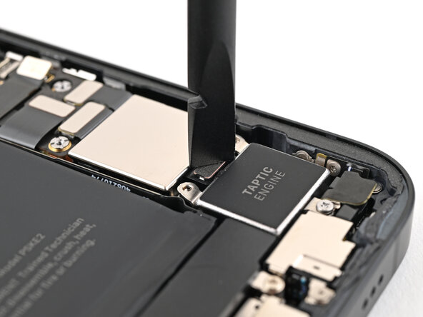
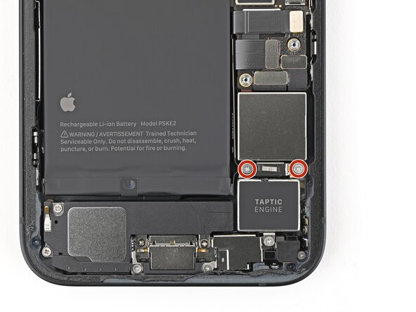
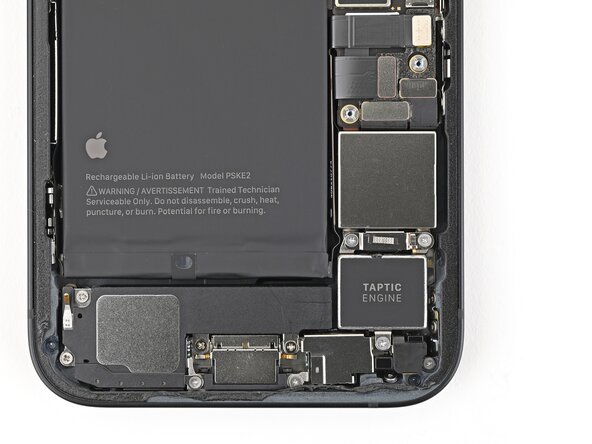
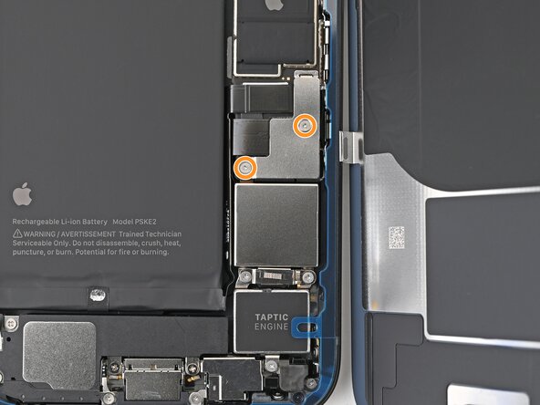
- Use a Phillips screwdriver to remove the two 2.2 mm‑long screws securing the Taptic Engine connector cover.
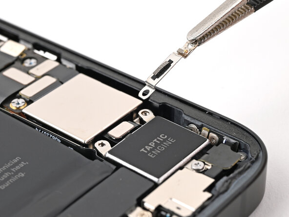
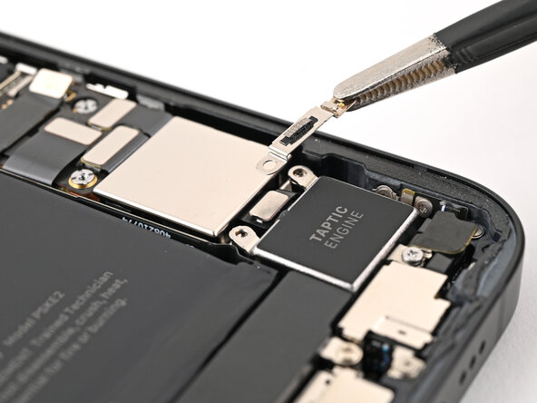
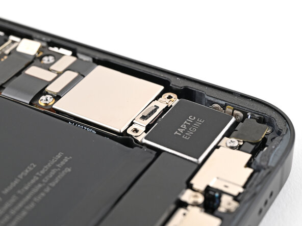
- Use tweezers or your fingers to remove the Taptic Engine connector cover.
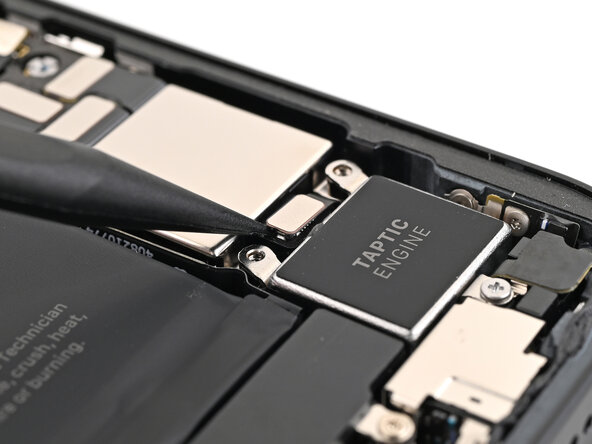
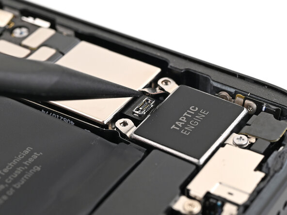
- Use the tip of a spudger to pry up and disconnect the Taptic Engine press connector.
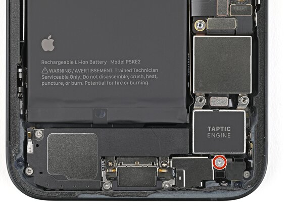
- Use a Phillips screwdriver to remove the 2.1 mm‑long screw securing the Taptic Engine.
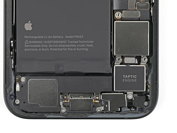
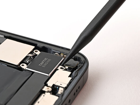
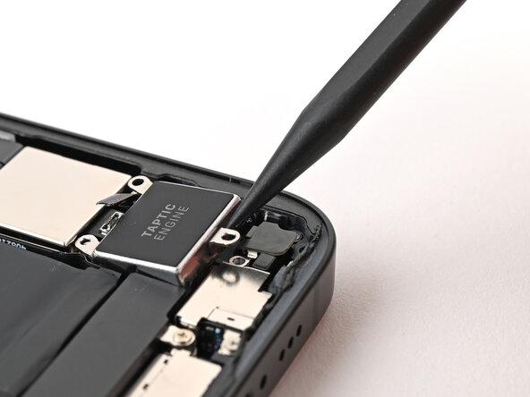
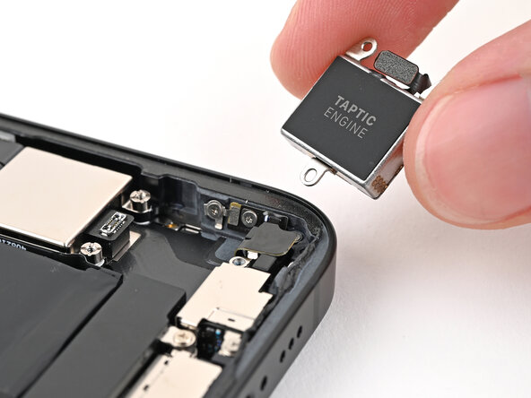
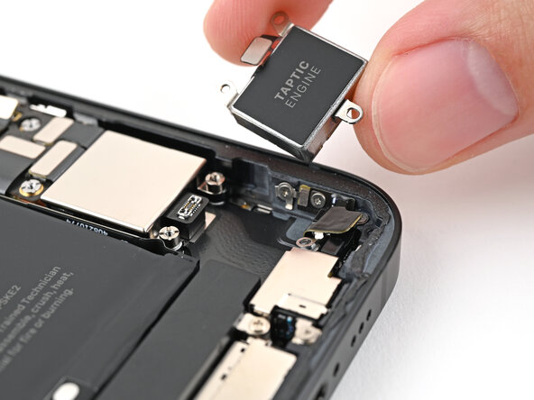
- Use the tip of a spudger to lift the Taptic Engine out of the frame until you can grip it with your fingers.
- Remove the Taptic Engine.
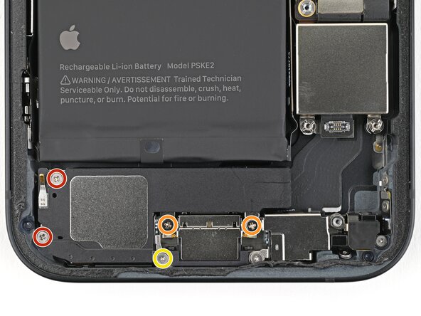
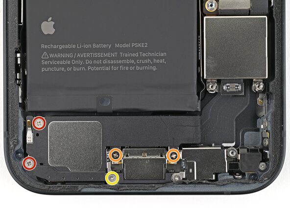
- Use a Phillips screwdriver to remove the four screws securing the loudspeaker:
- Two 1.4 mm‑long screws
- Two 1.7 mm‑long screws
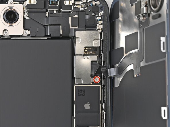
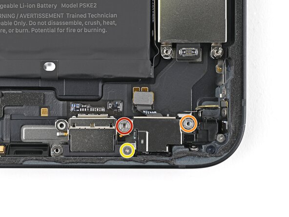
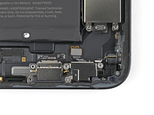
- Use a tri-point Y000 screwdriver to remove the 1.3 mm‑long screw.
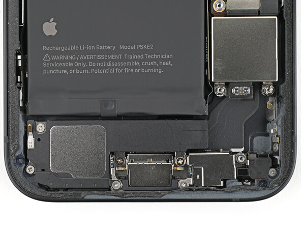
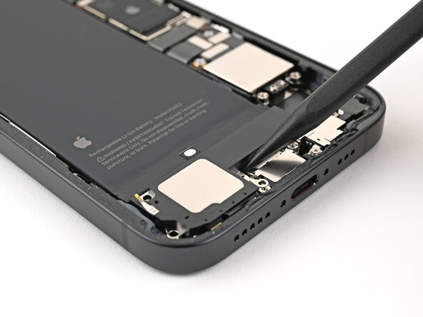
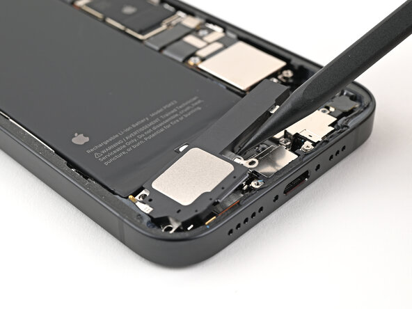
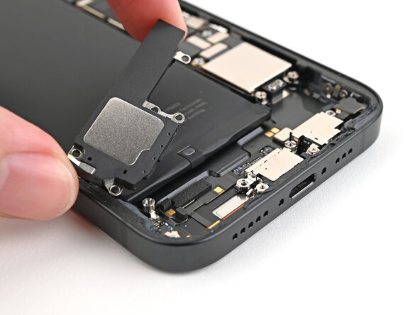
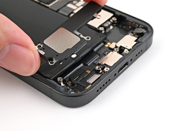
- Use the point of the spudger to lift the loudspeaker out of the frame and remove it.
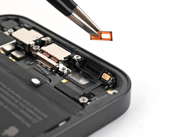
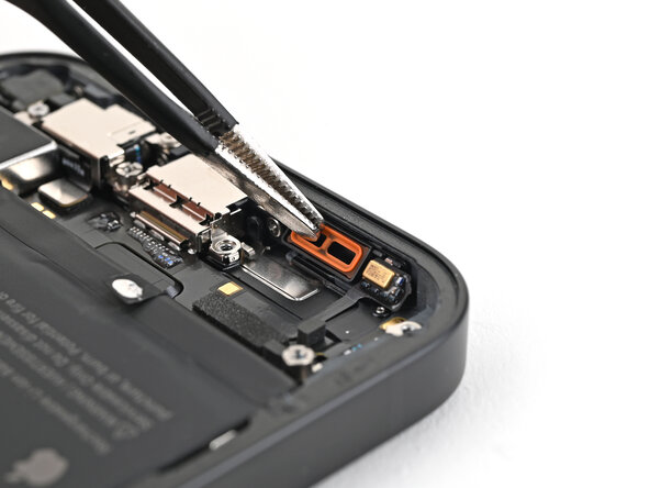
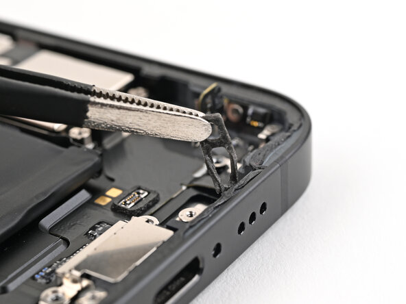
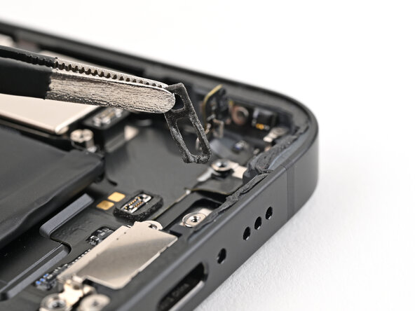
- If the orange loudspeaker gasket fell out during disassembly, use tweezers to place it back into the sound channel.
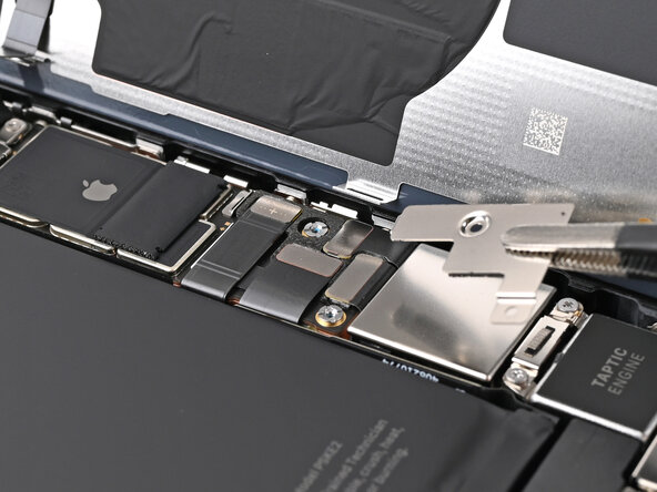
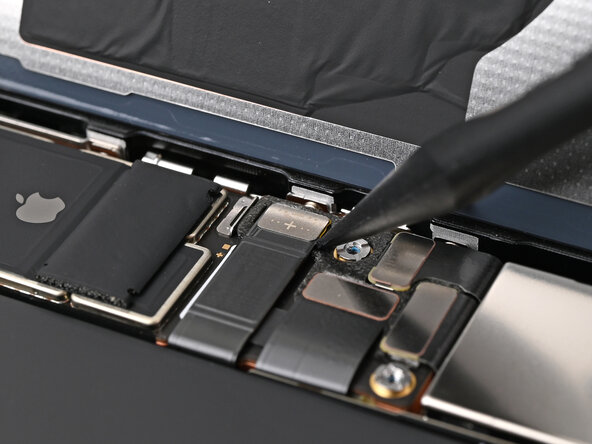
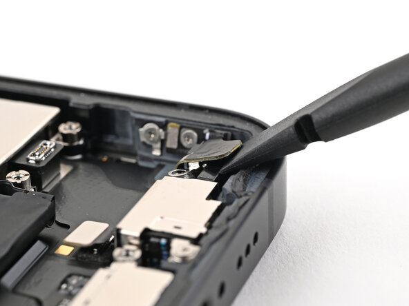
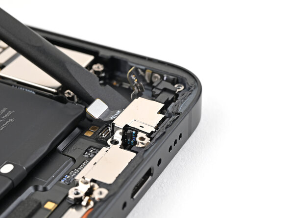
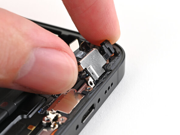
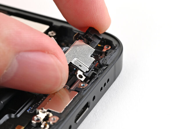
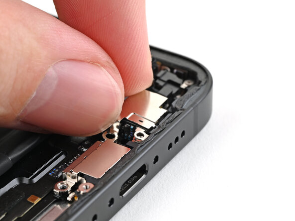
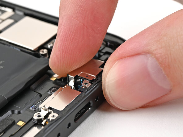
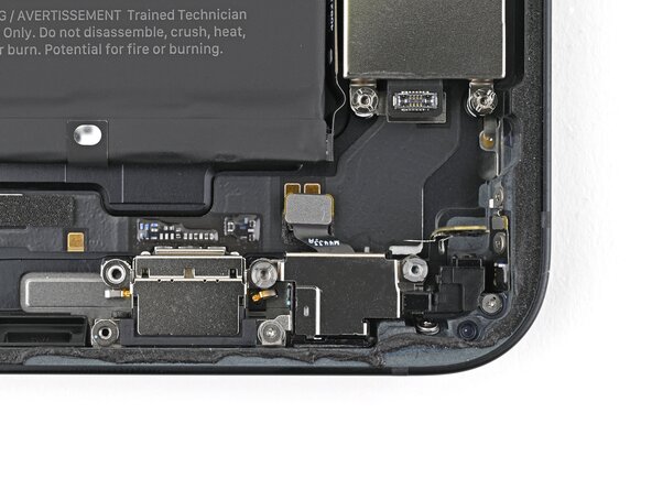
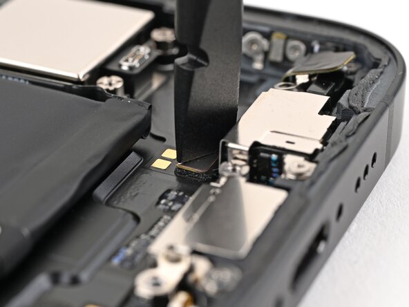
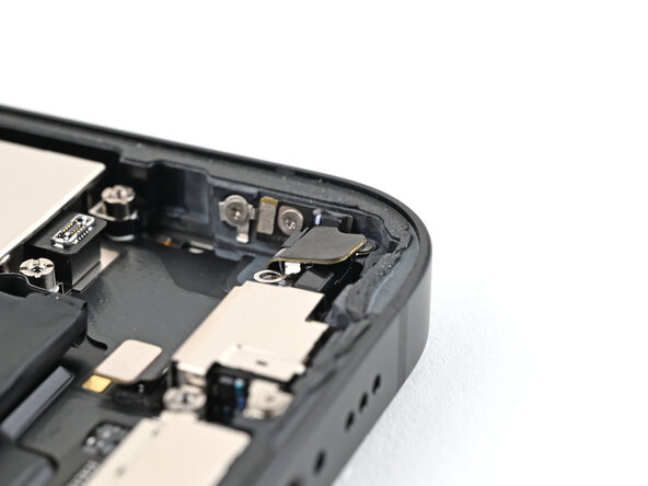
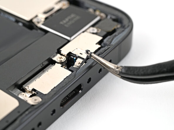
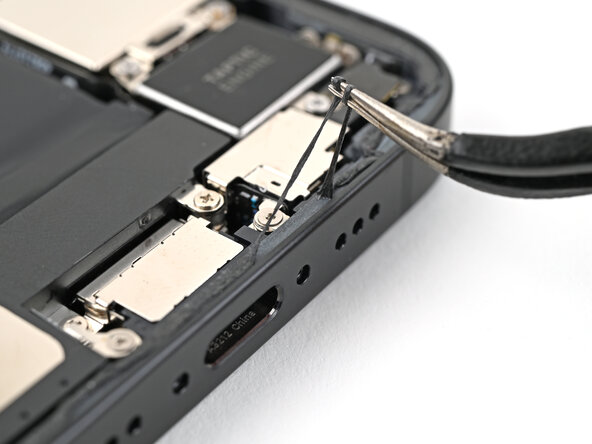
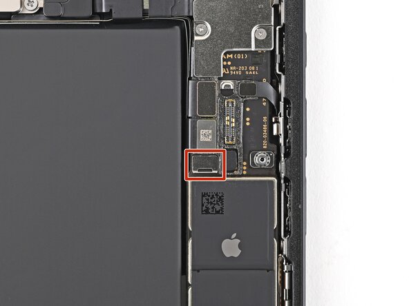
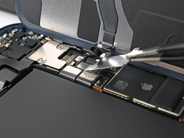
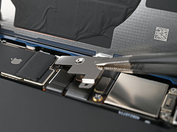
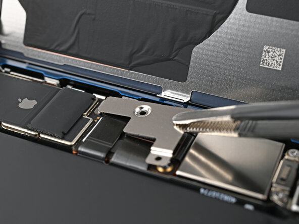
- Insert the flat end of a spudger between the screw cover and the microphone.
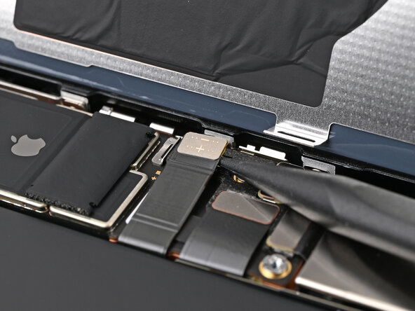
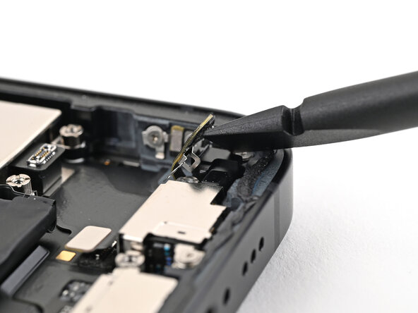
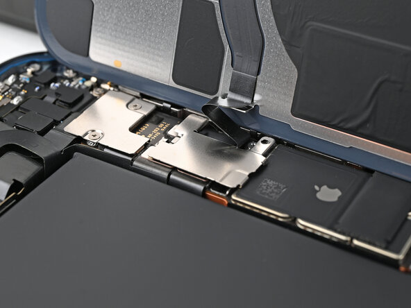
- Twist the spudger to separate the adhesive under the cover and release its metal clip.
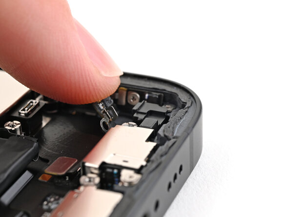
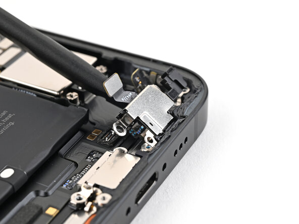
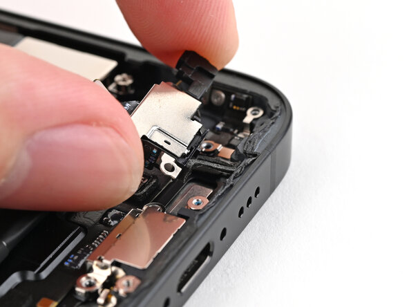
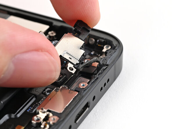
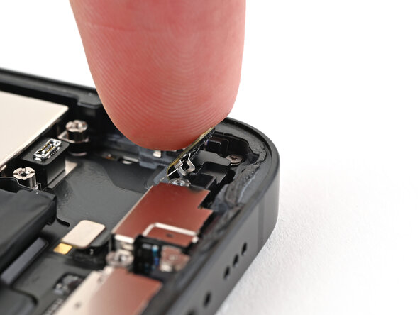
- Use your finger to gently bend the cover toward the top of the phone and reveal the remaining standoff screw.
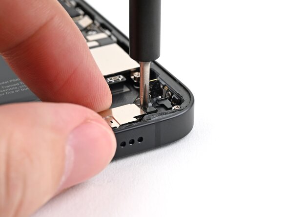
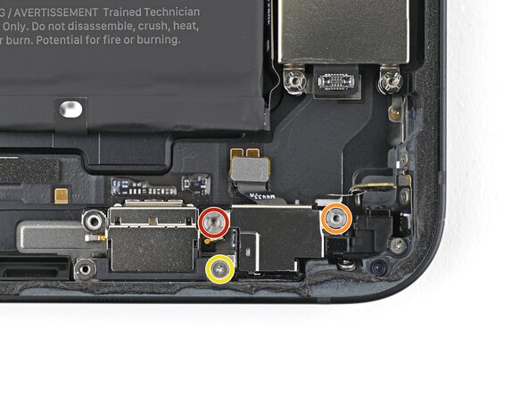
- Use a standoff screwdriver to remove two screws securing the microphone:
- One 3.0 mm‑long screw
- One 2.8 mm‑long screw
- Use a tri-point Y000 screwdriver to remove the 1.3 mm‑long screw securing the microphone.
- Use the flat end of a spudger to lift the microphone enough to grip it with your fingers.
- Pull the microphone away from the frame to separate the adhesive.
- Remove the microphone.
- Congratulations on completing disassembly! The remaining steps will show you how to reassemble your device.
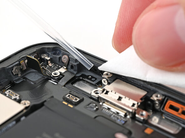
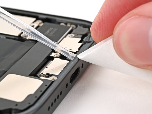
- Use tweezers or your fingers to remove the old adhesive from the bottom of the frame.
- If there's adhesive residue on the frame, use high concentration isopropyl alcohol (greater than 90%) and a coffee filter or lint-free cloth to clean it.
- If your microphone comes with adhesive installed, skip the next two steps.
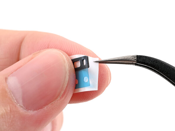
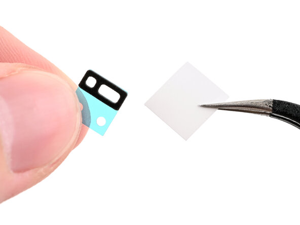
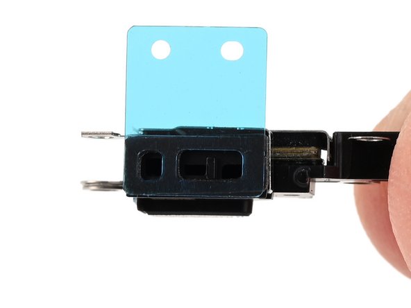
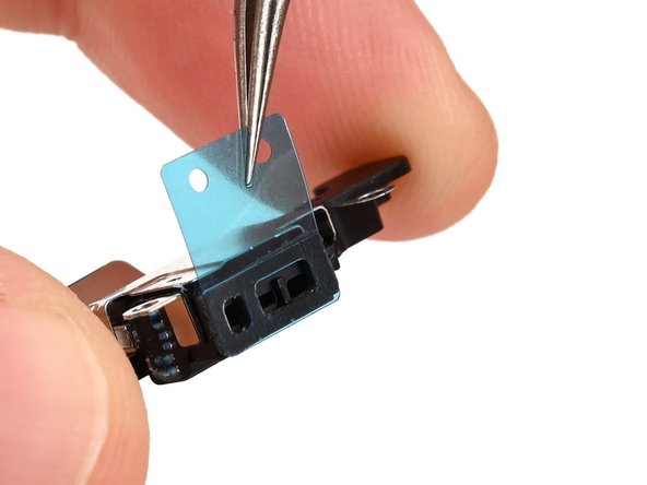
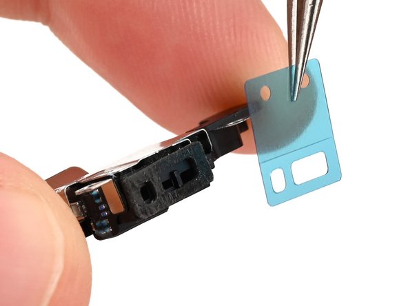
- While holding the microphone adhesive with one hand, use your fingers or a pair of tweezers to remove the white liner from the adhesive.
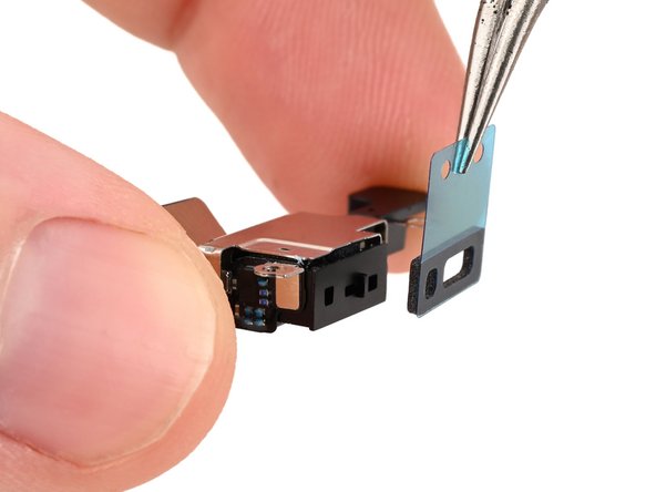
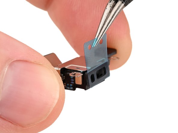
- Hold the microphone so the metal side is facing up.
- Apply the adhesive to the microphone with the pull tab pointing up.
- Remove the blue liner from the microphone adhesive.
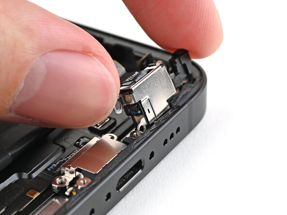
- Insert the microphone at a downward angle so the adhesive adheres firmly to the frame around the sound channel.
- Press the microphone firmly into place.
- While pressing the microphone against the frame, use a standoff screwdriver to install two screws securing the microphone:
- One 3.0 mm‑long screw
- One 2.8 mm‑long screw
- Use a tri-point Y000 screwdriver to install the one 1.0 mm‑long screw securing the microphone.
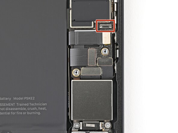
- Use the flat end of a spudger to connect the microphone press connector.
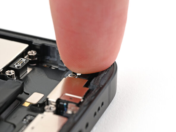
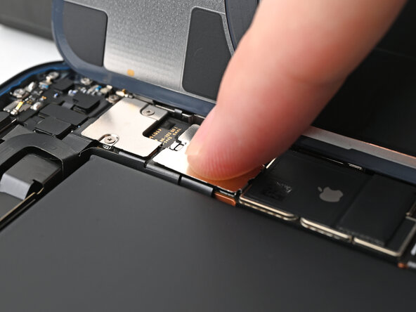
- Use your finger to press the screw cover back into place.
- You should hear and feel a "click" when the clip engages.
- If the remaining adhesive on the screw cover isn't sticky enough, replace it with a small piece of double sided tape, like Tesa Tape.
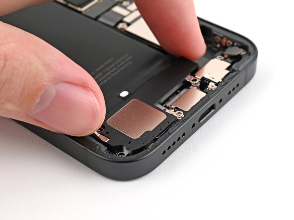
- Place the loudspeaker into its cutout in the frame.
- Use a Phillips screwdriver to install four of the screws securing the loudspeaker:
- Two 1.4 mm‑long screws
- Two 1.7 mm‑long screws
- Use a tri-point Y000 screwdriver to install one 1.3 mm‑long screw.
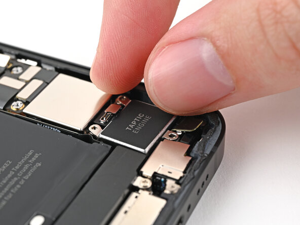
- Place the Taptic Engine into its slot in the frame.
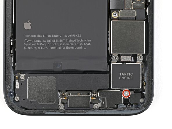
- Use a Phillips screwdriver to install the 2.1 mm‑long screw securing the Taptic Engine.
- Use the flat end of a spudger to connect the Taptic Engine press connector.
- Place the cover over the Taptic Engine connector.
- Use a Phillips screwdriver to install the two 2.2 mm‑long screws securing the Taptic Engine connector cover.
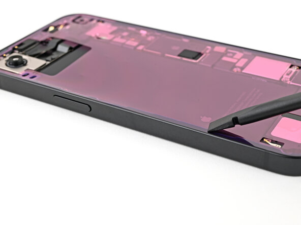
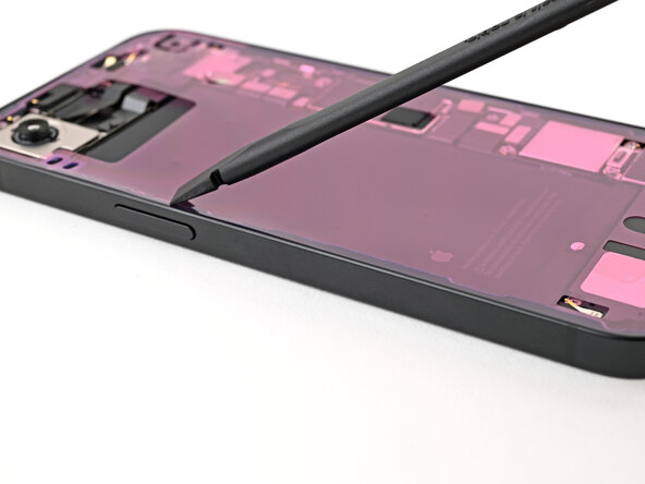
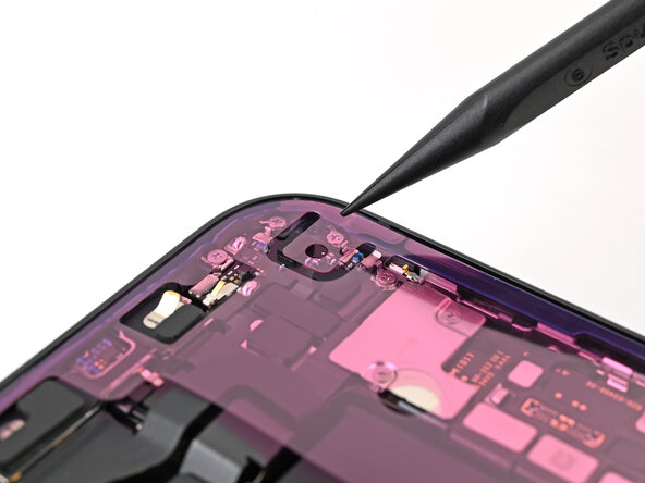
- Use tweezers to remove the adhesive around the perimeter of the frame.
- You may need to bunch up the adhesive with the point of a spudger before gripping it with tweezers.
- Use a coffee filter or a lint‑free cloth and high‑concentration isopropyl alcohol (>90%) to clean off any adhesive residue.
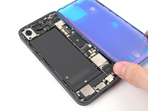
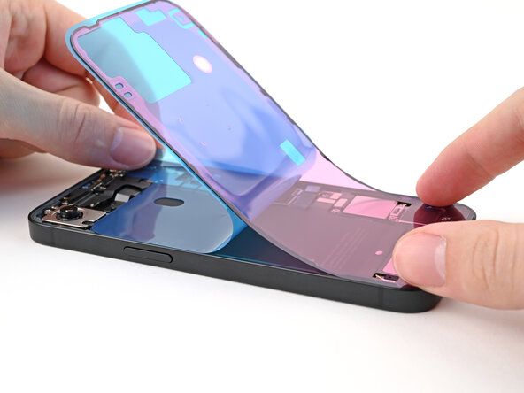
- Orient your replacement adhesive over the frame with the larger blue liner on the underside and its pull tab in the bottom-right corner.
- The color of your liner and the pull tab locations may be different on your adhesive.
- Use features such as the camera cutout and notches along the edges to visualize how the adhesive will lay in the frame.
- Once the adhesive is pressed into place, you can't reposition it—you'll have to remove it and start over with new adhesive.
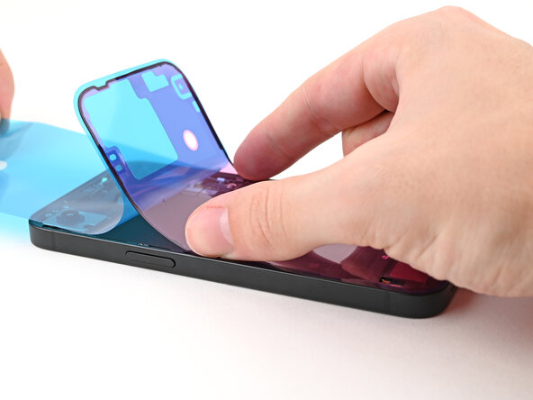
- Use the pull tab to begin peeling the back liner off the adhesive starting from the bottom, but don't remove the liner all the way.
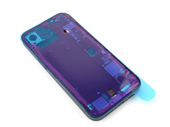
- Hold the blue liner out of the way and align the adhesive with the bottom edge of the iPhone.
- Lay the bottom edge of the adhesive into its recess in the frame, making sure the iPhone's spring contacts are aligned with their cutouts in the liner.
- Continue peeling the back liner off the adhesive while pressing the adhesive into place along the edges of the iPhone's frame.
- If you correctly aligned the lower edge of the adhesive, the side and top edges will fall perfectly into place. If the adhesive is misaligned, remove it and start over with new adhesive.
- If your adhesive is misaligned and you don't have another set handy, it's okay to temporarily put your iPhone back together and use it normally without any adhesive, but keep in mind that your iPhone's water resistance will be compromised until you install new adhesive.
- Use the flat end of a spudger to press the adhesive into place around the perimeter of the frame.
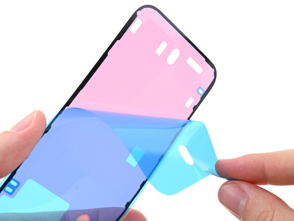
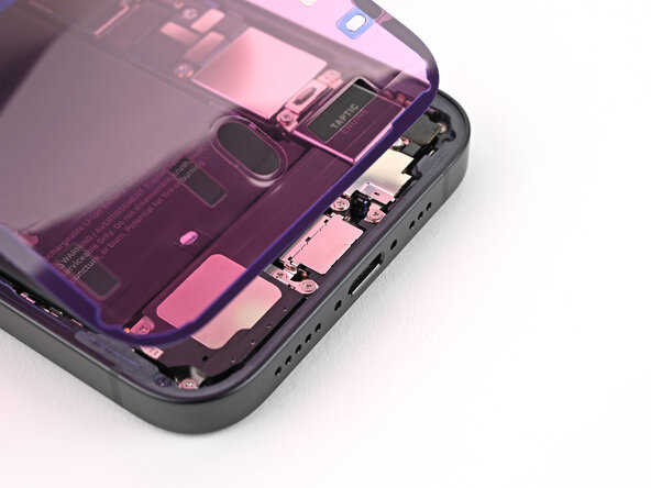
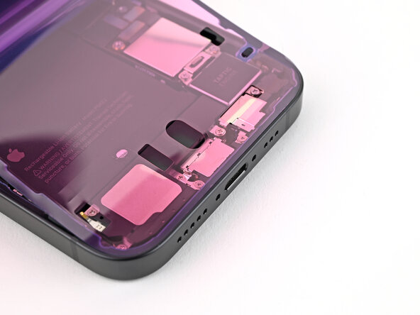
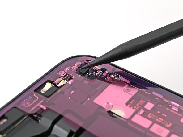
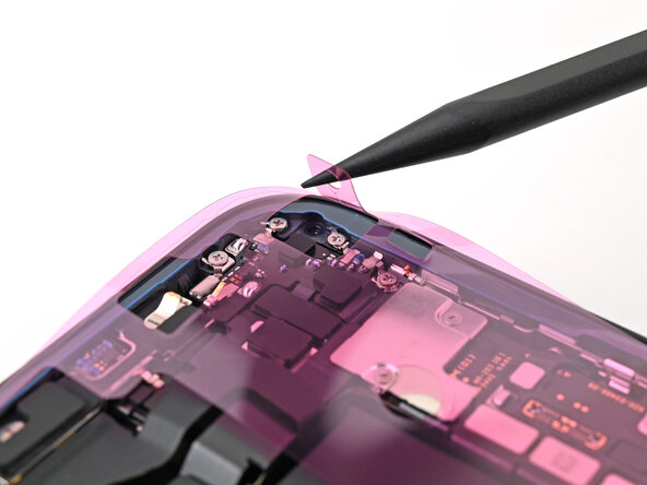
- Use the tip of a spudger to lift up the pull tab on the top right corner of the pink adhesive liner until you can grip it with your fingers.
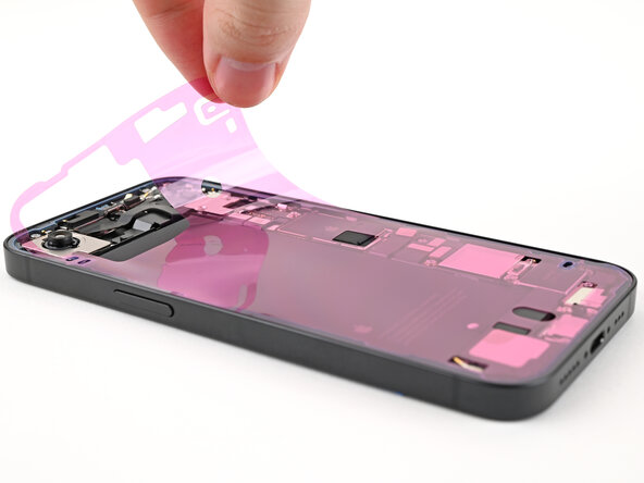
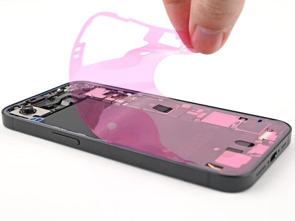
- Use the pull tab to peel the pink liner off the frame and expose the secondary blue liners.
- Prop up the back glass along the right edge of your iPhone, using a box or similar sturdy object to support the glass.
- Use the flat end of a spudger or your finger to connect the charging coil press connector, then the battery press connector.
- Place the middle connector cover over the wireless charging coil press connector so it slightly overhangs the slot on the logic board for the bottom clip.
- Use your finger to press the cover down on the logic board.
- While pressing it down, slide the cover upward so both metal clips slot into their spots in the logic board.
- Use tweezers to place the top of the lower connector cover over its slot in the logic board.
- Lay the lower connector cover over the press connector.
- Use a tri-point Y000 screwdriver to install the 1.0 mm‑long screw securing the middle connector cover.
- Use a tri-point Y000 screwdriver to install the two 1.3 mm‑long screws securing the lower connector cover.
- Use tweezers to grip the pull tabs on the three blue liners and peel them off to expose the adhesive.
- You may need to hold the back glass above the frame without it touching the adhesive to remove the liner along the right edge.
- Hold the back glass above the phone and align it with the frame.
- Lay the back glass straight down onto the frame and press until the clips engage.
- Press around the perimeter of the back glass to engage all clips.
- To help the adhesive bond, apply heat to the edges of the back glass using an iOpener, hair dryer, or heat gun until it's hot to the touch.
- Firmly press around the perimeter of the back glass. If you have screen vise clamps, use them to strengthen the bond of your new adhesive. If not, keep reading for more ways to secure the back glass.
- To evenly compress your iPhone and strengthen the bond of the back glass to the frame, you need to account for the camera bump.
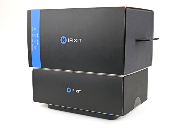
- If you have the box your iPhone came in, take the lid and place it on a flat surface.
- If you don't have your original box, skip this step for an alternate method.
- Place your iPhone screen-side-up in the lid of your box with the camera bump in its recess.
- Find something close to the size of your iPhone, but taller than the sides of the box. Stack it on top of the iPhone, followed by a few heavy objects.
- Leave the objects in place for at least thirty minutes. The lighter the objects, the longer they should be left. Ideally, leave them stacked overnight.
- If you don't have the original box for your iPhone, follow the next three steps for another method to evenly compress the back glass.
- Place the iPhone screen-side-down on a soft, flat surface.
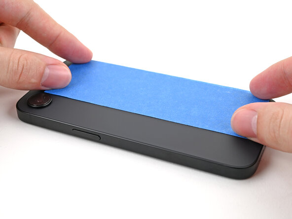
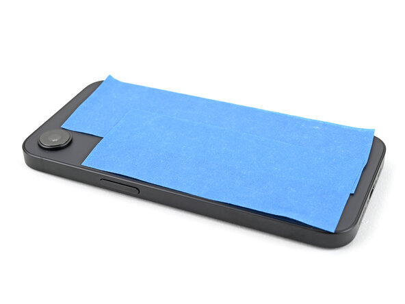
- Apply tape to the back glass to protect its finish.
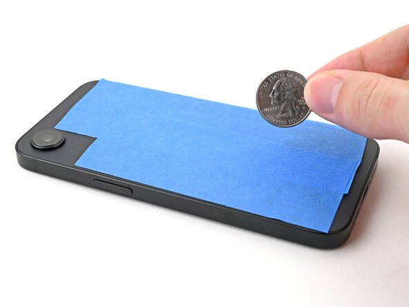
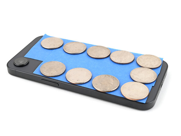
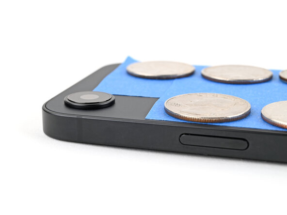
- Place one layer of coins or similarly thick objects on the tape along the edges of the back glass.
- Depending on the thickness of the coins, you might need multiple layers.
- Evenly distribute the coins and make sure they are at least as thick as the camera bump.
- Stack multiple books or other heavy objects on your iPhone.
- The coins may leave an impression on the bottom object, so don't use anything valuable.
- Leave the objects in place for at least thirty minutes. The lighter the objects, the longer they should be left. Ideally, leave them stacked overnight.
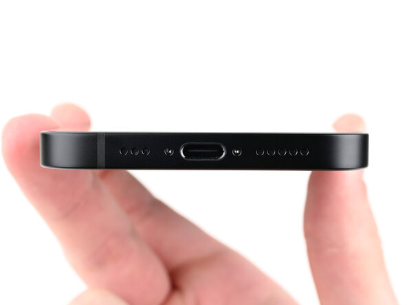
- Use a P2 pentalobe screwdriver to install the two 7.8 mm‑long screws on either side of the charging port.