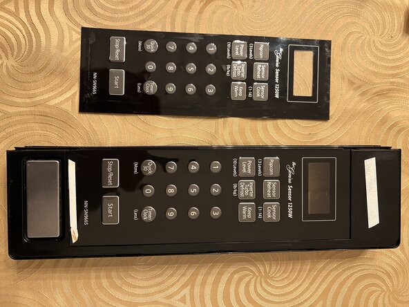
Panasonic Microwave NN-SN966S Membrane Switches Replacement
ID: 213188
Description: The membrane switches that are used for the...
Steps:
- WARNING: HIGH VOLTAGE HAZARD. Unplug the power cord and leave it unplugged for at least two minutes before removing the outer case. The front panel display should be blank. If it is still showing the time or any other part of it is lit, then the oven is still plugged in.
- IMPORTANT: Do not touch the parts inside the oven marked with red boxes, even when it is unplugged. These can hold a voltage of 2,000 V or more for some time. Avoid touching them with your fingers or any metal tool that lacks insulation. Do not insert any wire or tool inside them. There is no need to touch these parts in these instructions.
- Disclaimer: Repairing a microwave yourself can be hazardous. If you are not comfortable working around high-voltage electronics, it is recommended to take the unit to a qualified service technician.
- Remove five screws from the rear of the oven. Some or all will be Torx Security or Tamper Resistant size 20 (TS20 or TR20). Others may be Philips #2.
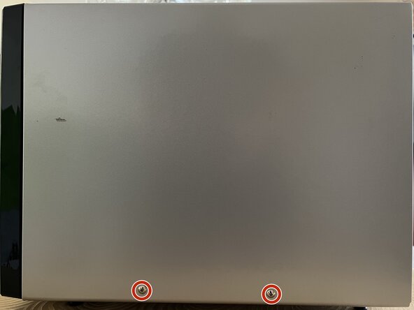
- Remove two Philips #2 screws from the right side of the oven. These screws are usually different from the ones on the rear so keep them separate or label them.
- Slide the outer case towards the rear of the oven and then lift it straight up. Be careful of the edges of the case as they are sharp and may cause injury. It is a good idea to wear gloves to do this. Also be careful that the edges of the case do not touch internal components during removal as this can damage them.
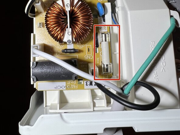
- While you have the cover off, it is a good idea to reposition the fuse near the power cord. Over time some metal oxide can form between the fuse and the contacts, which can result in the fuse becoming hot. This can eventually melt the fuse causing it to fail. Lifting the fuse out of the fuse holder and putting it back will help remove any oxide.
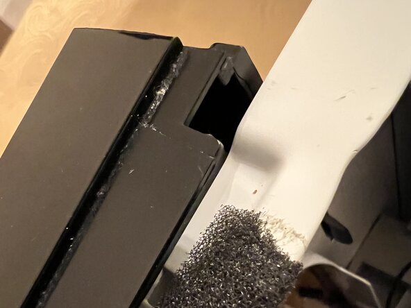
- The last two pictures show how to slide the molding around power cord up and then away from the back panel to gain better access to the fuse.
- If you need to replace the fuse look for part number F62308F20AP (originally F62308F00AP). It is a 6 mm x 30 mm (0.24 x 1.18 inch) 20 amp slow blow fuse. It can also be called a 1.25 inch fuse.
- Disconnect four white wire connectors (marked with red squares) from the circuit board. All are different so they cannot be confused. Top to bottom the connectors are labeled: CN3 with blue and black wires; CN2 with yellow, purple, red, white and black wires; CN4 with grey, yellow, red and white wires; and CN1 with orange and black wires.
- Disconnect two spade connectors (marked with red circles) from the black plastic relay. The top position is the blue wire with a non-insulated connector and the bottom is the black wire with a plastic insulator around the connector.
- Remove one Philips grounding screw securing a wire and a metal tab to the oven frame behind the front panel half way up the side of the oven. This screw has fine (narrow) threads.
- Remove a second Philips screw securing a metal bracket to the back of the control panel behind the top edge. This screw has coarse (wide) threads.
- Slide the front control panel straight up a fraction of an inch and then lift it off the frame of the oven. A metal tab at the bottom of the panel secures it to the bottom of the frame.
- Lift the two small tabs at each end of the black connector marked CN5 where the flexible green membrane switch is plugged in.
- Lift the loop of flexible green membrane switch to unplug it from the black connector. You can use a pencil under the loop to lift it evenly. When reconnecting the replacement membrane switch you can bend it the over the pencil to help plug it in.
- In two places (marked with red arrows) use a flat blade screwdriver to gently bend the plastic cover away from the metal mounting bracket. Plastic tabs on the inside of the housing hold the bracket in place. Moving both tabs out of the way allows the bracket to be rotated away from the housing a small amount.
- To remove the circuit board and mounting bracket completely, in two places on the other side (marked with orange arrows) repeat the same process to separate that side of the bracket from the housing. With both sides free you can lift the bracket and circuit board out of the housing.
- With a flat blade screwdriver lift up thirteen metal tabs inside the edges of the plastic housing so that they stand up against the inside of the housing. This allows the metal trim to be separated from the front of the housing.
- Insert a flat blade screwdriver under the edge of the metal trim and gently lift it away from the plastic housing. Start near the Stop/Reset button and slowly lift the trim from the housing. There is double sided tape under it so a little force is needed. Work around the end of the trim and then up the long side to the other end.
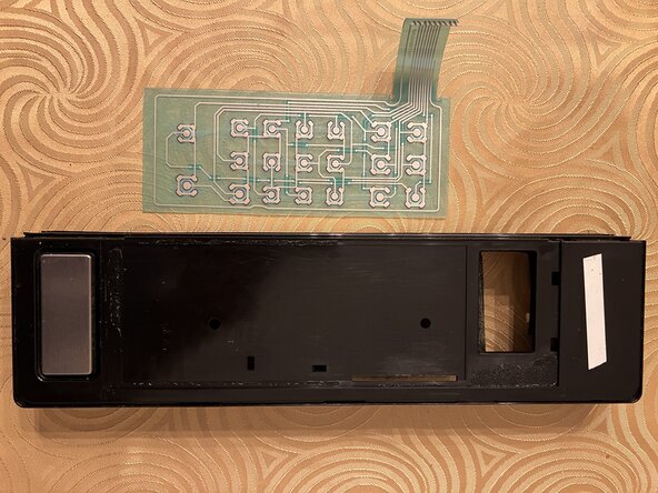
- Peel off the plastic cover sheet with the embossed buttons from the housing. Starting near the display end may be easier. This exposes the membrane switch flexible circuit board underneath. The second image shows an example of a deformed metal dome (red arrow points at the switch for the Power Level button in this case).
- Then peel the membrane switch flexible circuit board off the plastic housing.
- Look at the plastic housing where the membrane switch and plastic cover were attached. There is a recessed section where the plastic cover was that includes the display. Inside of this there is a deeper recessed section where the membrane switch was attached. The replacement membrane switch and cover need to fit into each of these recessed areas.
- Peel the protective film off the sticky back of the replacement membrane switch.
- Insert the narrow strip of the flexible circuit board that plugs into the black connector on the circuit board into the open slot on the right edge of the plastic housing below the display opening.
- Align the edge of the membrane switch with the strip through the slot along the right edge of the deeper recess in the plastic housing. Check that the top and bottom corners are inside the recess, then flatten the membrane onto the housing making sure all the edges are inside the recessed section.
- Peel the protective film from the sticky back of the plastic cover. Start at the end with the tab sticking out with the part number on.
- Align the edge of the cover against the right edge of the shallow recess along the right side of the housing. Check that the clear part of the cover is where the display opening is, and that the top and bottom corners are inside the recess, then flatten the membrane onto the housing making sure all the edges are inside the recessed section.
- Peel the protective film from the front of the plastic cover.
- Remove any strips of double sided tape stuck to the front of old plastic cover and transfer them to the same locations on the new plastic cover. There should be three pieces of tape. The narrow piece above the door open button needs to be at the very bottom edge of the cover.
- Align the metal trim with the front of the plastic housing and insert each of the metal tabs into the corresponding slots. Start at one end and work your way around the long edge to the other end. If the tabs don't easily slide into the slots you can use the flat blade screwdriver to straighten them by pressing them against a flat surface.
- Once all the metal tabs are inserted into the slots turn the plastic housing over and begin bending all the metal tabs over. Push down on the housing as you bend each tab over to make sure the trim is pushed flat against the housing.
- You can now reassemble the oven by following the instructions in reverse order from Step 9 back to Step 1.