Weston Ranger 9 Lightmeter CdS Cell and Battery Replacement
ID: 213318
Description: IMPORTANT NOTE: STANDBY ON THIS REPAIR...
Steps:
- Be sure to remove any batteries from the compartment and leave the battery bay open.
- Remove the exposure dial by removing the large screw in the middle counter-clockwise.
- Remove the cover.
- Remove the 2 tiny nuts that hold the needle lock which also releases the dials.
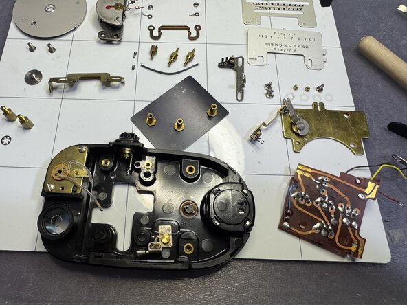
- Remove the large brass standoffs to free the galvanometer, and stand it on its bottom as shown in the first picture. Be VERY careful with the needle and counterweights. You will need to move the needle towards the middle cutout for the counterweights to pass.
- Desolder the red wire from the meter. Make sure you remove the bottom nylon washers which are easy to miss. The other two nylon washers should have been sandwiched between the two aluminium dial plates.
- Remove the two tiny round nuts that hold the brass plate as well as the screw in the top left corner and remove the brass plate being careful with the contacts and the moving arm in the right.
- Finally remove the HI-LO switch mechanism by removing the large flat screws that hold the slider. Be extra careful with the tiny plunger on the knob's side. If you turn the meter over, the plunger and the tiny spring will come out and probably get lost.
- Slide the circuit board towards the right side and upwards. Avoid damaging the battery test contacts on the bottom left side. The board should slide upwards without much pressure to these contacts.
- Pull the circuit up and out so you can cut or desolder the CdS leads. This is a good time to remove the tiny plunger and its spring (see what they look like near the galvanometer in the second picture).
- Remove the circuit board, and at this point the back cover should also naturally fall off, and two of the standoffs will be held by the tiny bolts that hold the calibration cover.
- Your parts at this point should resemble the last picture in this step.
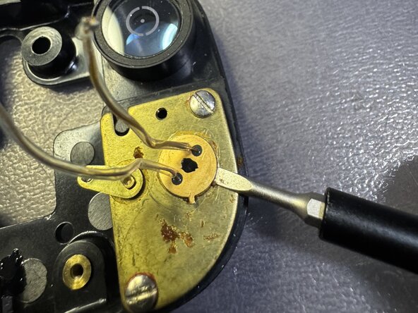
- Loosen the adhesive with acetone and a QTip. Be careful not to saturate the cell in a way that the acetone may leak into the ND filter under the cell and/or onto the lens. Scrape the softened glue with a flat screwdriver.
- Slide the flathead carefully under the rim and pry the old cell carefully from all directions. Notice the small pile of glue I needed to scrape off, in order to be able to slide the flat head under the ring.
- Remove the old CdS, being careful not to allow dirt or glue into the filer or lens. If you suspect dirt, remove the 2 screws and clear with a photographic puffer. Do not touch or clean the filer or the lens, unless you have special photographic cleaning equipment such as those used for lenses, sensors and reflex mirrors.
- I suggest you place a piece of electrical tape to cover the CdS hole whilst you complete the rest of the steps.
- 3D Print the CdS Holder and the Cap. The STL files are attached as documents to this guide.
- Insert the new CdS from the bottom and push with something soft like an eraser, leaving about 1mm from the bottom brim of the holder, as shown in the first picture.
- Bend the leads through the channels, and fill the cavity with E6000 glue or similar soft glue. Overflow a little bit so you can also glue the cap at this time. Let cure 24H before handling again.
- IMPORTANT: Even though the picture shows the glued cell, you are NOT gluing the CdS cell at this time. Only measuring splicing and soldering the CdS leads.
- The new CdS leads are shorter than the original, so you will need to to extend them with a soft and thin wire. I used 24-26ga wire-wrapping cable.
- Make sure to first wrap the CdS exposed leads with heat-shrink tubing and leave about 1/4-1/8in exposed for wiring. Then wrap and secure the wire-wrap and solder in place. Cover union with heat shrink tubing as well.
- Bend the leads as shown but do not glue the CdS into place yet. Wrap the wirewrap leads around the viewfinder and solder the ends into the original posts.
- Be sure to keep the cell aligned. In my build I did not print a tab (I painted a straight line with a marker). On the published STL file, you have tab which should always be pointing straight to the top, in order to keep the CdS aligned correctly to the lens.
- Clean the contacts with metal polisher and then wash with alcohol and finish by using a good lubricating and protecting contact lceaner such as DeoxIT D100L or similar. I coated the whole PCB with a thin coat of DeoxIT and a QTip (I use lint-less QTips that are common for makeup).
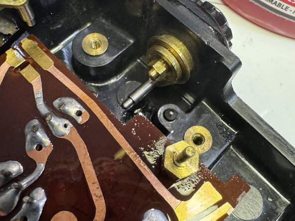
- Route the wires as shown and then slide the PCB back into place, being very careful not to bend the battery test contacts.
- Screw the 3 standoffs that hold the PCB.
- At this point, you can carefully glue the CdS into place making sure the tab is pointing upwards. Make sure that no glue drips onto the filter nor the lens below the cell!
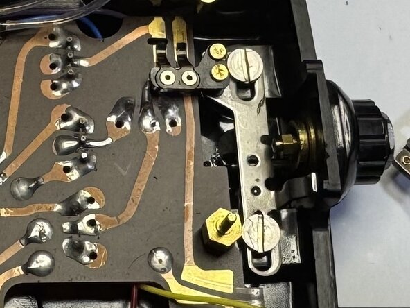
- Insert plunger spring in its cavity near the knob side as shown in the first picture.
- Insert the plunger with the tip upwards as shown.
- Replace the HI-LO switch. Be careful with the spring contacts and bend them slightly if not making proper contact.
- Before you insert the first brass plate, make sure that the black bow spring on the left side is in its place. You can insert it after the plate but it's harder.
- There is a wound-up spring in the thick brass plate that you must preload. What I did was move the spring end all the way to the left, and then used a thin piece of electrical tape to hold it into place.
- Insert the brass plate into place. Make sure it "clicks" into position in the bottom two standoffs. Look at the red arrows in the second picture. Those tiny cylindrical protrusions click snugly into the holes of the brass plate.
- Do this and hold the plate in place whilst screwing the tiny round brass nuts. Tighten the tiny round nuts carefully about 1/4 to 1/2 turn. Do not over tighten because the thread is very thin and brass threads are easily damaged. Screw the flathead screw in the top left last.
- The last picture shows the brass plate in place. Notice the tape is removed and the position of the spring now rests on the standoff (bottom right of the frame). Pay no attention the nylon washers in the picture, they don't go here but rather on top of the brass needle lock slider (next step).
- Place the brass slider as shown in the picture. Place the first two nylon washers on each of the tiny posts above the brass slider. On the left side, make sure the slider tab is placed in tween the bow spring and the battery check tab. This allows the needle to unlock when checking battery level.
- Place the galvanometer as shown to facilitate the soldering of the red lead.
- Carefully slide the galvanometer back into place. Important things to note:
- Move the needle acrefully towards the center so that the counterweights can fit inside the cutout in the middle.
- Make sure nothing is under the Galvanometer base (especially any wires and the metal tab with the yellow wire).
- The ZERO screw is aligned perfectly at the top or bottom of the vertical.
- The ZERO tab on the galvanometer is perfectly aligned with the tip of the ZERO screw.
- Hand-tighten the brass standoffs that hold the galvanometer into place. Don't forget the corrugated pressure washer on the left post, and the yellow wire (ground) tab, which also has a pressure washer. Test the ZERO screw and make sure the needle moves back and forth as you rotate the ZERO screw. Don't force anything !!!
- Disconnect the black wire from the battery compartment center (+) contact.
- The original black wire should reach the regulator and be soldered into the VOUT pad.
- Wire an extension yellow wire from the ground terminal of the battery compartment to the ground tab of the regulator.
- Wire a new color wire (blue in the picture) from the center (+) tab to the VIN pad of the regulator, and leave the control pad unconnected.
- Place a 6V supply to the terminals, and adjust the regulator pot to exactly 2.7V. You need to be patient as the V stabilizes when you remove the screwdriver and it's VERY sensitive. Use a professional plastic pot adjustment tool to make your life easier in this step.
- 3D print the Regulator holder and glue diagonally as shown in the picture. Use E6000 or similar adhesive.
- Slide the pre-adjusted regulator into place and fix with a small dab of hot glue as shown.
- Make sure not to move the regulator's pot when sliding the regulator into place, and make sure to test the voltage again after it's all done (before you hot glue it !)
- Route the wires above the battery compartment as shown.
- NOTHING should be behind the galvanometer, especially a wire. Hot glue the wires to the top if you think they will move. There is almost zero clearance behind the galvanometer and the coil is VERY delicate.
- Print the battery adapter from the corresponding STL file. Use PETG if possible but probably PLA can be used since you shouldn't be exposing your meter to high temperatures anyway!
- Insert the two CR1632 with the + side down towards the center contact. One first, then the next, also with the + side down. Insert the battery adapter with the notch downwards and towards the top of the meter so it clears the bottom contact.
- Place the 10mm spring into the smaller hole at the top, and screw on the lid.
- Remove the tiny hex screws from the back cover. Be extra careful not not scratch the anodized aluminium plate. Be mindful that this meter is designed to be used vertically so when calibrating take special care the meter is vertical and straight up. The counter-weights of the galvanometer will give you a false reading if not.
- If you installed the correct CdS you can use my pot positions as a starting point. Then print or view the attached circuit diagram titled Weston Ranger 9 Calibration. This will show you the pots involved for HI, LO and Battery scale.
- YMMV. I used a modern Sekonic which has an EV range of 3 to 17 as a reference meter. Some people suggest to use reflected light using an 18% gray reference card. Others suggest white, and others use a 4700° K tungsten lamp with a dimmer through an 80B type filter. I am not an expert but what I did was the following:
- Dimmed the lights of a room to get 3 EV @ 100ASA from the Sekonic off a white wall.
- Calibrated in the LO scale using R3 and R1.
- Went outside in the sun and chose a spot off a white item that measured 16 on the Sekonic.
- Calibrated the HI scale using R4 and R1
- Finally I held the meter upright and callibrated the battery at exactly the red dot using R5. This must be done last because R4 and R2 are involved and must be calibrated first.