Leitz Trinocular Head FSA (512 738) Teardown
ID: 220140
Description: The Leitz Trinocular Head FSA catalogue number...
Steps:
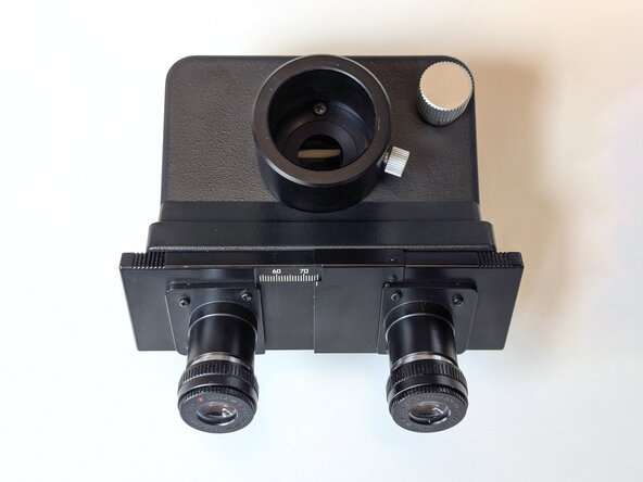
- Start by adjusting the interpupillary distance to the smallest value. The eyepiece shields should move forward and expose 2 flathead screws.
- Remove the eyepieces if present.
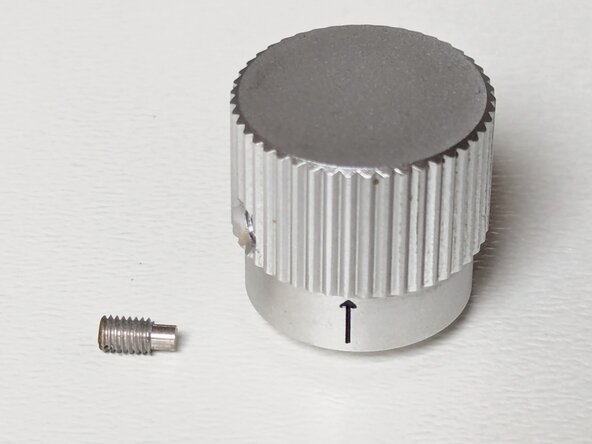
- Remove the M3x4.5 2.5 mm flat head screw and pull off the prism selector knob by pulling straight up.
- As with many of the fasteners on Leitz microscopes, it is made of brass. Take some care not to mangle or strip the fastener's head.
- Remove the 3 M3x5.5 Phillips 1 screws from the trinocular tube.
- When using an iFixit screwdriver set, using a J1 combined with a smaller bit driver allows for easier access, as the screws are located in an internal recess of the trinocular tube.
- Take care not to drop the screws, as the prism assembly is exposed underneath and can be damaged easily.
- Remove the 4 flat head screws.
- 2x M3x8 5mm flat head.
- 2x M3x6 5mm flat head.
- Take care not to drop the screws, as the prism assembly is exposed underneath and can be damaged easily.
- The front assembly is loose and can be lifted out of the head.
- Take care when lifting out the front assembly, as the prism assembly is exposed and can be damaged easily.
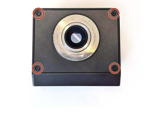
- Turn over the main head assembly.
- Remove the 4 M3x6 5 mm flat head screws.
- Removing the bottom cover undoes the factory-set optical alignment. However, the little side-to-side adjustments have very little to no perceivable effect on the generated image.
- Remove the 2 M3x8 Phillips 1 screws.
- When using an iFixit screwdriver set, using a J1 combined with a smaller bit driver allows for easier access.
- Removing the beamsplitter prism assembly undoes the factory-set optical alignment. However, the little side-to-side adjustments have very little to no perceivable effect on the generated image.
- The beamsplitter prism assembly has no stable position without having one prism side touching a surface. Placement on a clean Kimwipe or microfibre cloth is recommended.
- Loosen the M3x6 5mm flat head screw on the counter pinion assembly to loosen the tension on the timing belt.
- Remove the 2.5 mm grub screw and brass clamp to free the timing belt.
- The timing belt is a 4T5/245 (4 mm width, 5 mm T-type pitch, 245 mm circumference, 49 teeth).
- This beamsplitter prism assembly is fitted with a black aftermarket timing belt. The original timing belt is coloured yellow to light brown.