Siemens TT911 Toaster Heating Chamber Disassembly
ID: 220201
Description: In this guide, I will show how to disassemble...
Steps:
- Siemens TT911 from the side.
- First, remove the crumb tray.
- Pry the rear cover upward with a firm tug.
- The side panels must be pushed toward the back. This requires force.
- If necessary, tap the front edge with the side of your hand or a wooden block. ATTENTION! The aluminum scratches very easily.
- The side panels are hooked into slots using tabs. The side panels must be slid about 1 cm.
- The side panels can then be lifted away, starting from the bottom.
- The pins are inserted into the teardrop-shaped openings in the plastic.
- Belt bracket
- Belt
- Unhook the belt in this direction. The belt bracket fits tightly. It is best to use two small screwdrivers, positioning them on the left and right sides of the belt bracket to pry it off.
- The control unit can only be removed in the next step once the belt is released.
- The control unit can be pried off by prying on both sides with a screwdriver.
- Pry on both sides and then pry up. This will also disconnect the electrical contacts. It may be a bit stiff.
- You now have the control unit in your hand as a complete part.
- Clean the electromagnet. Both the metal rod and the cylinder. Do not forget the underside of the rod!
- Release the two clips.
- Release the two clips to detach the outer wheel from the white gear.
- Housing and mount for the bimetallic switch. It prevents the toaster from closing during operation or while it is still hot.
- If the PCB is still plugged in, you can measure the resistance of the holding magnet: 22k Ohm
- The two heating elements have a combined resistance of 56 Ohm.
- Optocoupler with triac switches the magnet. Original K3023P. Cheaper replacement MOC3023.
- Tilt switch.
- The white switch is controlled by a bimetal in the heating element and prevents the toaster from closing if it is still warm.
- 230V AC power input.
- If the electromagnet can no longer hold the toast carriage down permanently, the magnet and the corresponding metal pin are usually dirty. It is also possible that a replacement of the capacitors is necessary. First, only replace the green and orange marked ones.
- Capacitor X2 0.047 uF 275V
- Capacitor X2 0.47 uF 305V
- Capacitor 470 uF 16 V
- Capacitor X2 0.1 uF 275V
- The black tab must engage with the white lever. Otherwise, the temperature-dependent cover interlock will not work.
- Clip in the PCB.
- The two white parts must interlock. Be careful! Do not bend or break them.
- Insert the white washer, then the spring and the cover knob on top.
- Place the part with the PCB over it and snap into place.
- Check again that the two white parts have slid into each other.
- There are arrows on the plastic indicating the positions of the main switch, the temperature lever, and the white gear.
- The orientation of the cover and the control knob must match.
- The bimetal must be slid into the white switch.
- Clip the control unit back into place.
- The small white gear can be turned (eccentrically) to adjust the tension of the belt.
- Hook the belt back into the belt holder.
- Belt holder.
- Direction in which the belt must be pressed on.
- Reattach the side panels.
- When installing the rear cover, the pin must be threaded into the white opening.
- The base plate only needs to be opened if you want to replace the cable.
- There are 4 clips that must be opened. These break off easily!
- To disassemble the internal components of the toaster, go to the following guide: TT911 heating element disassembly
- By releasing the Torx screw (back and front), the cover cap can be easily removed.
- Unplug the cover cap guide towards the front.
- Unhook the spring.
- Use one screwdriver to pry up each tab one by one and a second one to prevent it from snapping back. Proceed this way all the way around.
- Push back the four tabs and pry up the boiler room.
- Attention! The small tabs are very delicate. If they break, another fastening method must be considered. The control board is plugged onto these contacts and must fit precisely.
- Pry up the tabs only very slightly!
- All metal tabs must be bent straight all around in order to separate the metal plates. The more precisely you work, the easier it will be.
- When reassembling, make sure to install this guide correctly.
- Since I do not want to list every individual metal tab, here are a few more pictures for the subsequent reassembly without markings.
- Bimetallic lever to prevent the cover from snapping into place when the heating chamber is heated.
- Spring for centering the bread racks. These must be unhooked.
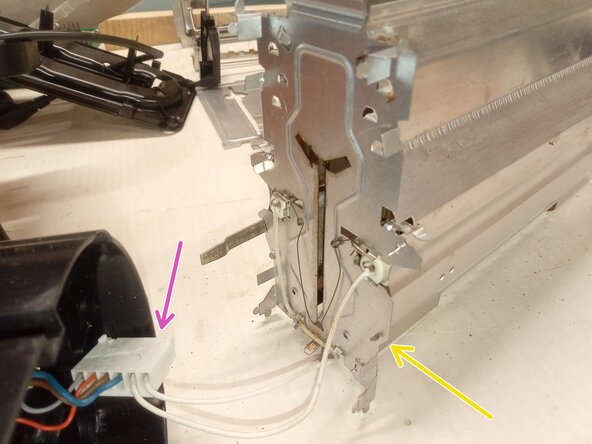
- Observe the cable routing and restore it in the same way.
- On the underside of the heating element is a tab that serves as a connector for the protective earth conductor. It is very important to bend this straight downward during assembly.
- It would be helpful to disconnect the two supply lines for the heating elements from the contact module. This requires two fine points or a "special tool."
- The individual parts can only be cleaned very well. This ensures optimal reflection of the heat.
- Assembly is best done with four hands; consider the arrangement and alignment of the components carefully.
- The bottom plate can be easily unclipped at 6 points using a flathead screwdriver.
- The middle plate must also be unclipped, specifically at three points. This requires quite a bit of force.
- The middle plate and the bottom plate do not need to be removed for the repair. The middle plate also contains the strain relief for the power cord. It is quite fiddly to reassemble this.