Replacing David Clark Aviation Headset Left Dome
ID: 23564
Description: I received this headset at a garage sale. At...
Steps:
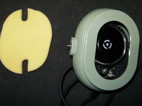
- Clearly visible damage on the left dome. Broken dome, missing retainer pin and clip as well as completely missing mic and mount as well as volume control button.
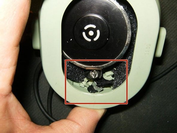
- Close up of the damaged dome.
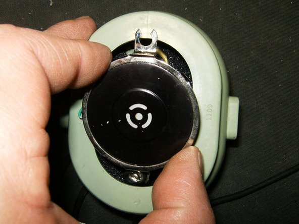
- This is the mounting hole for the boom mic
- Since this dome does not have any of the retainer pins or clips, it simply slides out of the fork
- This view shows the well worn filters (foam)
- This is the connector for the boom mic.
- One more view of the complete headset
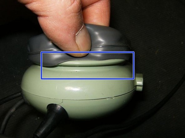
- Start removing the earseal by simply lifting it out of the groove in the dome.
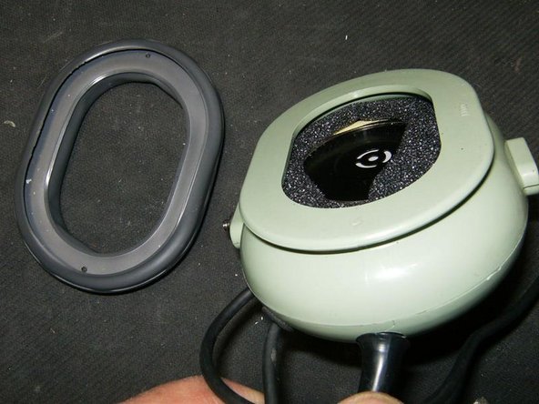
- Remove the earseal
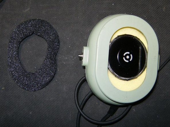
- Remove the foam filter
- The speaker is now visible with more foam filters
- Remove the next filter
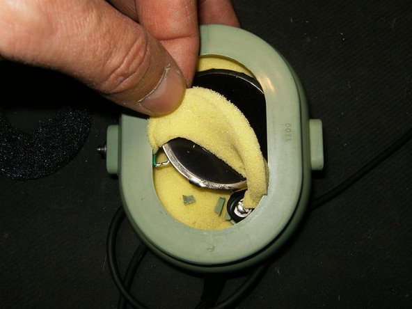
- one more filter removed shows the screws for the speaker.
- Remove the next filter. Notice the different shapes of the filters.
- After the filter removal, inside damage of the dome becomes visible. In this case the standoff for the speaker screw was broken off.
- Remove the mounting screw for the filter.
- Lift the speaker out of the dome. The wires are still attached, so do not try to pull to hard.
- Flip the speaker over to reveal the wire connection and the last filter. Originally this headset will only have three different foam filters
- This is the last foam filter. All the wiring will be beneath this filter
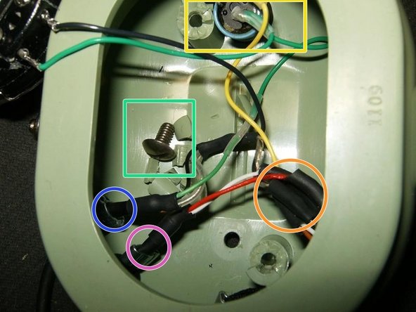
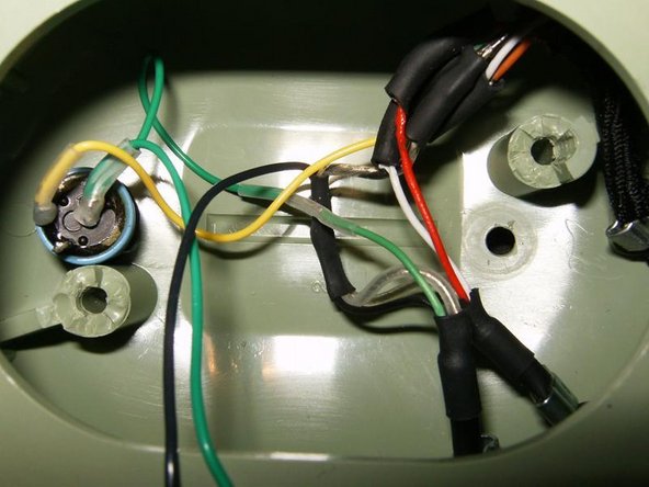
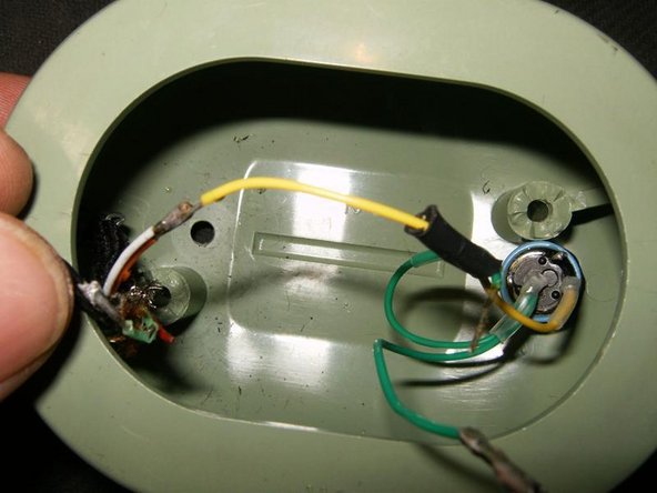
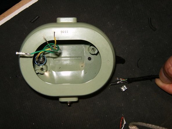
- Here is the complete wiring
- Crossover cable
- Microphone cable
- Main cable (Communication cord)
- Volume control
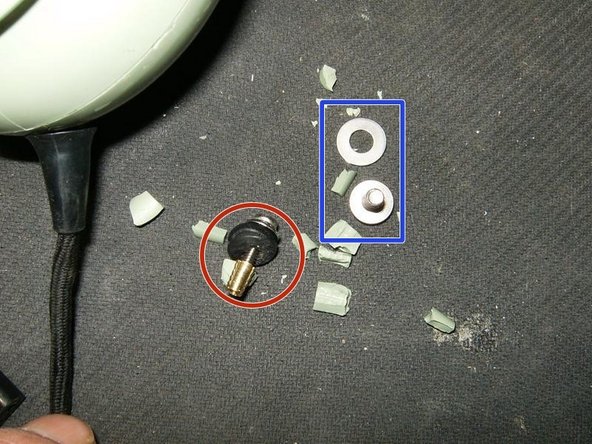
- and more broken pieces. The screw comes from the boom mic guide.
- Long screw was originally for the speaker, The short screw and washer are from the boom mic guide. Plenty of plastic from the broken standoff inside the dome.
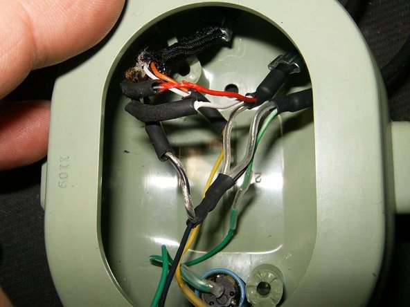
- One more look at all the wiring.
- and here a bit closer. This will be needed for reassembly.
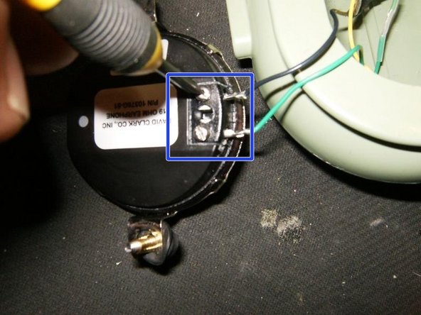
- Remove the speaker wire by loosening the two slotted screws
- Remove the speaker
- More views of the wiring.
- Here is the broken standoff with the missing plastic.
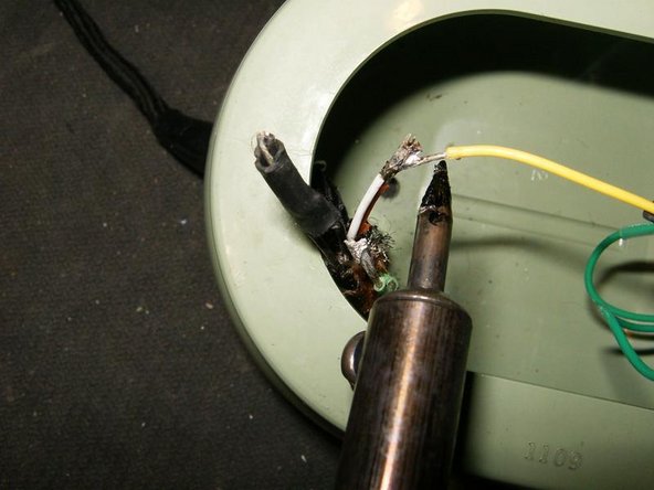
- First to remove the mic cable. All connections in this headset are soldered. If possible, slide the heat shrink off the soldered connections to separate them with a soldering iron
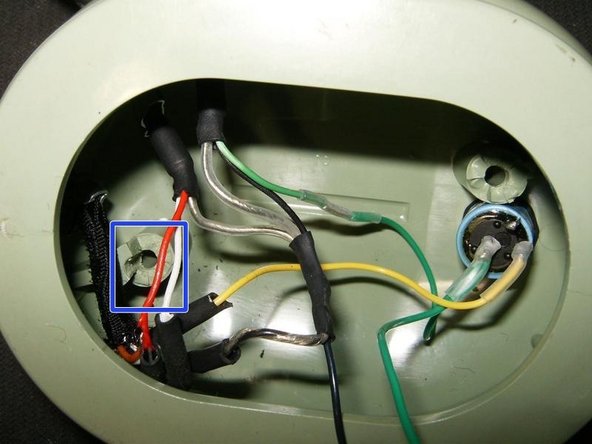
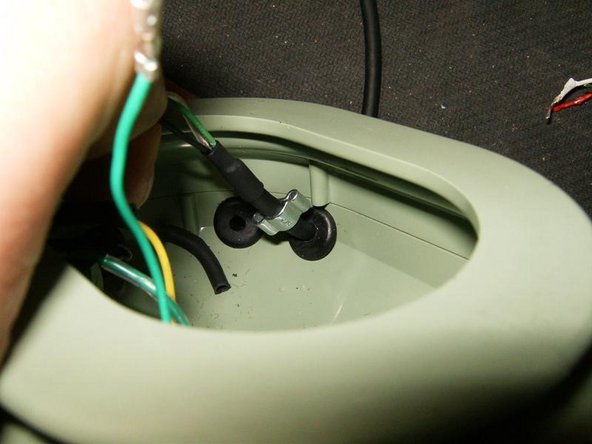
- these are the cord clips holding which prevent the cables from being pulled out of the dome.
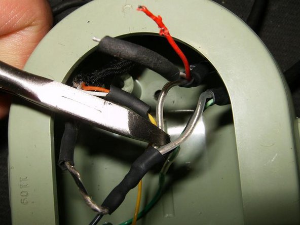
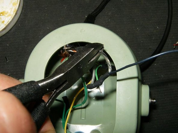
- The connections where the heat shrink tubing can not be removed, are cut with a pair of pliers.
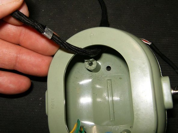
- With the mic cable connected, pull the cable inside the dome to gain easy access to the cord clip
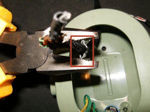
- Squeeze the cord clip with a pair of pliers.
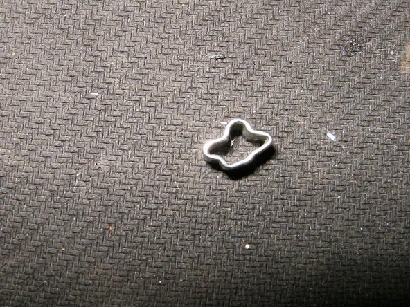
- Remove the cord clip
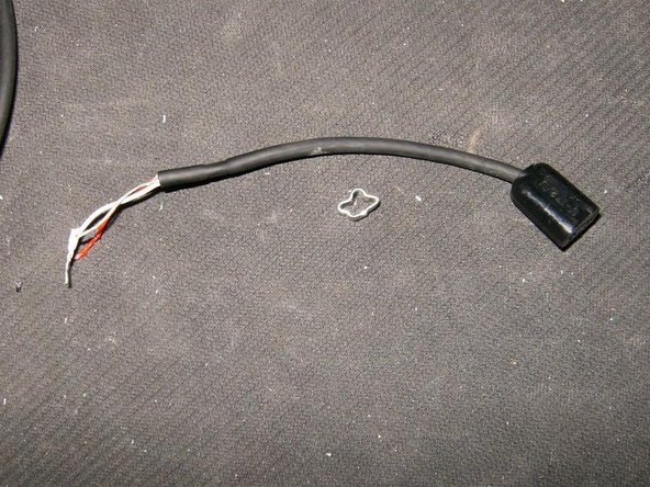
- Remove the mic cable
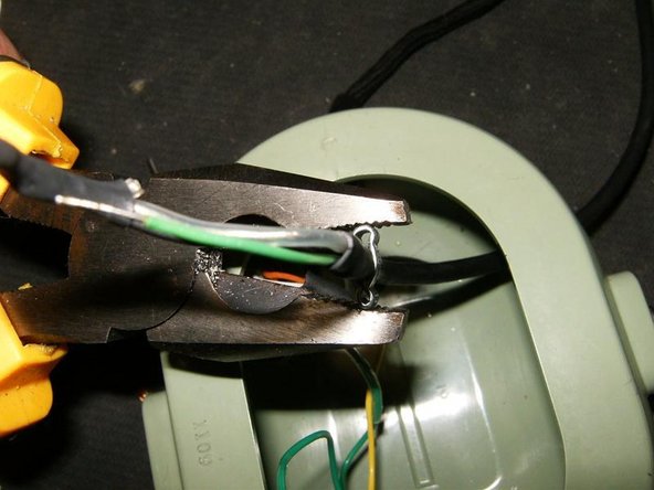
- Next remove the crossover cable.
- If the heatshrink tubing can not be removed from the connection, cut it with a pair of pliers.
- Pull the cable into the dome
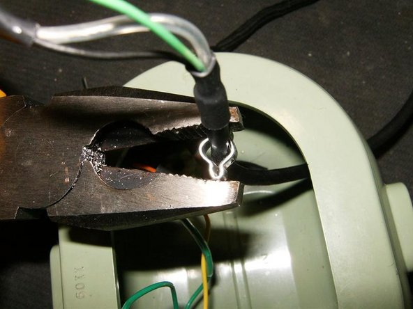
- Pull the crossover cable toward the inside of the dome to gain access to the cord clip
- Place a pair of pliers on the outside tabs of the cord clip
- by squeezing the pliers shut, the cord clip will expand and can then be easily removed.
- With the cord clip removed, simply pull the crossover cable out of the dome.
- The last connection is the main cable to the volume control potentiometer
- unsolder that connection (or cut with pair of pliers if unable the heatshrink tubing)
- Volume control and main cable are now disconnected .
- Pull the main cable into thedome to get access to the cord clip.
- Place a pair of pliers on the long tabs of the cord clip,
- by squeezing the pliers shut, the cord clip will widen and come loose
- remove the main cable.
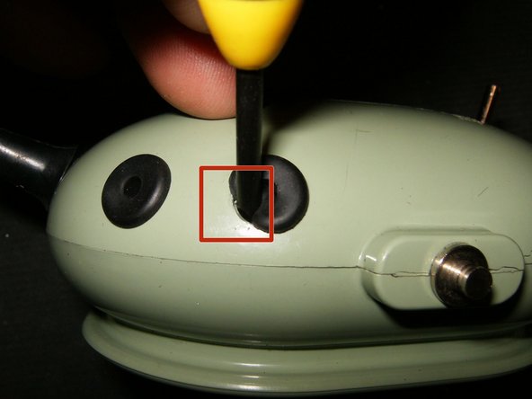
- Next use a small jewelers screwdriver and push on edge of the rubber grommet into the dome
- carefully work around the grommet pushing it gently into the dome.
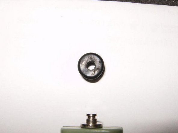
- Remove the grommet
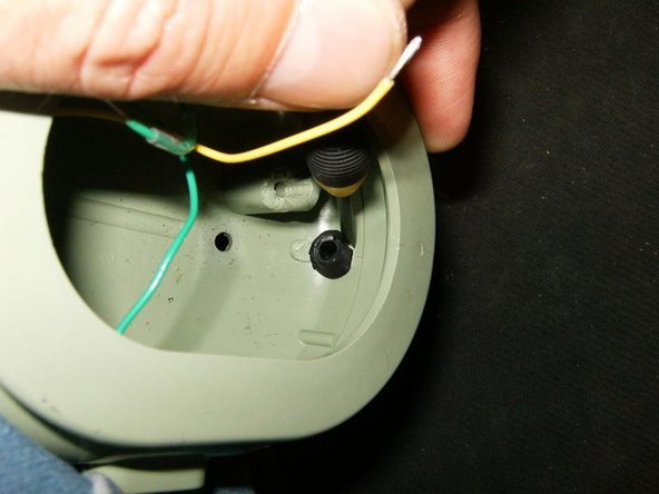
- Again use a small jewelers screw driver for the grommet of the crossover cable
- The elongated grommet for the main cable will have to be removed from the inside out.
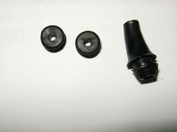
- Here are the two small grommets for the mic and crossover cable, as well as the elongated one for the main cable.
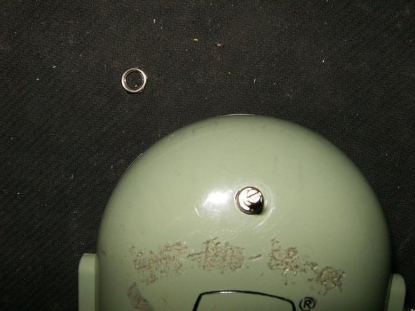
- The speaker control potentiometer is held in place with a 5/16 hex nut.
- remove the hex nut.
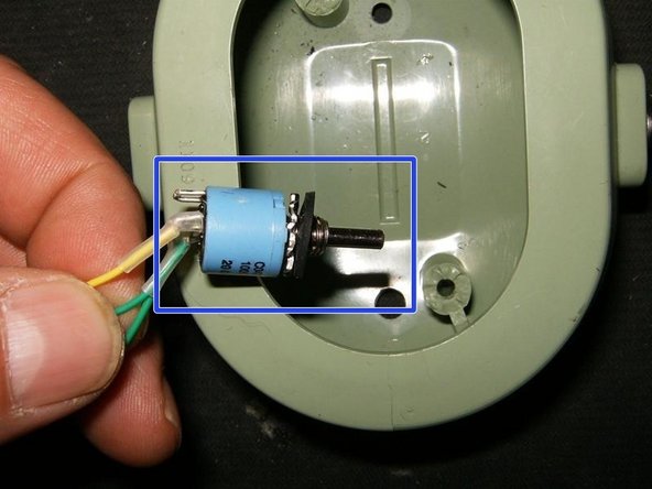
- Remove the volume control from the inside of the dome.
- All the cables and parts have now been removed. On the left is the replacement dome.
- Here is my replacement David Clark Aviation Headset Microphone Mic M101. this is not original for this model headset.
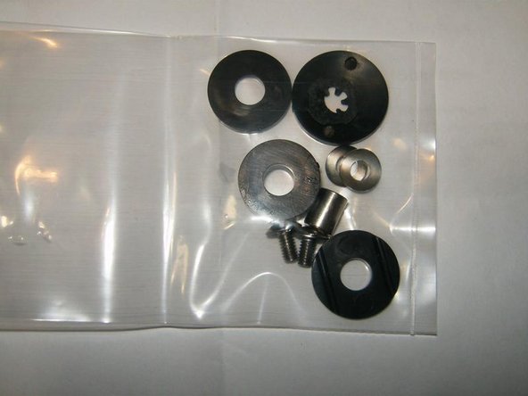
- Here is the new boom mic guide kit hardware.
- Each boom mic guide kit could be different, so follow the instructions the accompany the set.
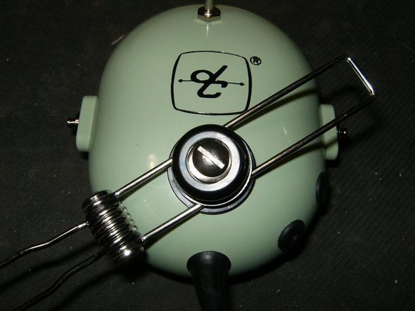
- Here is the boom mic guide mounted to the left dome. For the rest of the reassembly, follow this guide in reverse order.