MacBook Pro 13" Unibody Mid 2010 Keyboard Replacement
ID: 23632
Description: Use this guide to replace just your keyboard,...
Steps:
- Remove the following 10 screws securing the lower case to the MacBook Pro 13" Unibody:
- Seven 3 mm Phillips screws.
- Three 13.5 mm Phillips screws.
- Slightly lift the lower case and push it toward the rear of the computer to free the mounting tabs.
- Use a spudger to pry up the fan connector out of its socket on the logic board.
- It is useful to twist the spudger axially from beneath the fan cable wires to release the connector.
- The fan socket and the fan connector can be seen in the second and third pictures. Be careful not to break the plastic fan socket off the logic board as you use your spudger to lift the fan connector straight up and out of its socket. The layout of the logic board shown in the second picture may look slightly different than your machine but the fan socket is the same.
- Remove the following three screws:
- One 7 mm T6 Torx screw
- Two 5.4 mm T6 Torx screws
- Lift the fan out of the upper case.
- Grab the plastic pull tab secured to the display data cable lock and rotate it toward the DC-In side of the computer.
- Gently pull the display data cable connector away parallel to the board.
- Do not pull the connector upwards, or you may damage the connector.
- Remove the following two screws securing the display data cable bracket to the upper case:
- One 8.6 mm Phillips
- One 5.6 mm Phillips
- Lift the display data cable bracket out of the upper case.
- Use the flat end of a spudger to pry the subwoofer and right speaker connector up off the logic board.
- Pull the camera cable connector toward the optical drive to disconnect it from the logic board.
- This socket is metal and can be easily bent. Be sure to align the connector with its socket on the logic board before mating the two pieces.
- Use the flat end of a spudger to pry the optical drive, hard drive, and trackpad cable connectors up off the logic board.
- Use your fingernail or the tip of a spudger to flip up the cable retaining flap on the ZIF socket for the keyboard ribbon cable.
- Use your spudger to slide the keyboard ribbon cable out of its socket.
- Peel the small strip of black tape off the keyboard backlight ribbon cable socket.
- Use the tip of a spudger to flip up the cable retaining flap on the ZIF socket for the keyboard backlight ribbon cable.
- Use your spudger to slide the keyboard backlight ribbon cable out of its socket.
- Use the flat end of a spudger to pry the battery indicator cable connector up off the logic board.
- Use the tip of a spudger to pry the microphone off the adhesive attaching it to the upper case.
- Remove the following screws:
- Two 7 mm T6 Torx screws from the DC-In board
- Five 3.3 mm T6 Torx screws
- Two 4 mm T6 Torx screws
- Removing the battery before lifting out the logic board is not strictly required, but makes removing the logic board easier and safer. If you leave your battery in, be especially careful not to bend the logic board against the battery's case near its bar code.
- Remove the following Tri-point screws securing the battery to the upper case:
- One 5.5 mm Tri-point screw
- One 13.5 mm Tri-point screw
- Lift the battery out of the upper case.
- Lift the logic board from its left edge and raise it until the ports clear the side of the upper case.
- Pull the logic board away from the side of the upper case and remove it, minding the DC-In board that may get caught.
- For precautionary purposes, we advise that you disconnect the subwoofer connector from the logic board to avoid any electrical discharge. This step is optional and is not required.
- Remove the soft padding that may be on top and gently pull the connector up out of its socket on the logic board.
- It will be necessary to slide the small clear plastic cable retainer (boxed in red) glued to the logic board out of the way before disconnecting the camera cable. Be careful not to break any components off the board as you slide it away from the camera cable connector.
- Pull the camera cable connector toward the optical drive to disconnect it from the logic board.
- This socket is metal and can be easily bent. Be sure to align the connector with its socket on the logic board before mating the two pieces.
- Use the flat end of a spudger to pry the optical drive connector straight up off the logic board.
- Use the flat end of a spudger to pry the hard drive connector straight up off the logic board.
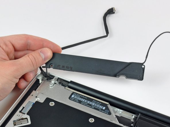
- Remove the following screws securing the subwoofer to the upper case:
- One 3.8 mm Phillips screw
- One 5 mm Phillips screw
- The subwoofer is still connected to the right speaker, so don't completely remove it just yet.
- Lift the subwoofer off the optical drive, and set it above the computer.
- Remove the two 10 mm Phillips screws securing the camera cable bracket to the upper case.
- The leftmost screw may remain captive in the camera cable.
- Lift the camera cable bracket out of the upper case.
- Remove the three 2.5 mm Phillips screws securing the optical drive to the upper case.
- Lift the optical drive from its right edge and pull it out of the computer.
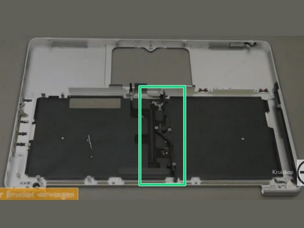
- Rotate the top case so that it looks like the top case in the picture.
- Remove the 10mm phillips #00 screw.
- Remove the 5mm phillips #00 screw.
- Remove and set aside the centre bracket.
- The pictures are captured from a YouTube video, but it does show the correct screws and part to remove.
- Carefully peel the black keyboard backlight from the upper case and remove it.
- It is best to start from the bottom right corner.
- Slide a spudger under the bottom right corner and slide the spudger up the right hand side of the backlight.
- Once you have the right hand side of the backlight loose, you can then use your fingers to gently peel the backlight from the keyboard.
- Remove the following screws:
- Two 3 mm PH00 screws from the power button.
- Sixty-seven 2mm PH000 screws from the keyboard.
- Gently lift out the keyboard (and the attached power button).