Disassembling the AEG 8000 series AP81UB25GG
ID: 237763
Description: The vacuum cleaner stopped providing power to...
Steps:
- First, remove the replacement battery, container, and filter. This can be done without a tool.
- Remove the rubber seal with tweezers or a small flathead screwdriver.
- Release the two thick Torx screws (see image for size).
- Release the decorative cover with a thin flathead screwdriver.
- Release the exposed Torx screw (see image for size).
- The motor housing cover can now be folded back and removed. Clips must be released.
- Bend the eyelets to the side; the electronics cover can now be folded back.
- Release the connector from the circuit board.
- CAUTION: The connector marked in orange has a tab. Do not pull on the cable, or the contacts will tear out of the connector.
- The circuit board is only held in place by clips and can be removed separately.
- Release the 4 thick Torx screws (see image for size).
- Remove the motor.
- When reassembling, place the filter fleece as shown in the image and route the cables through the slots marked in red.
- Release the thick Torx screws (see image for size)
- Release the thin Torx screws (size decreases from left to right, see image)
- Do not forget the metal washer for the container magnet during reassembly!
- The midframe can now be removed.
- Remove the plastic rail with the rubber lip, e.g., using a thin flathead screwdriver. Start at the bezel.
- Do not remove the rubber lip from the plastic rail; it is difficult to reinsert. This mistake was made in the second image.
- Remove the wheels, e.g., using a thin flathead screwdriver or combination pliers.
- Release all marked security Torx screws.
- The side parts can now be removed.
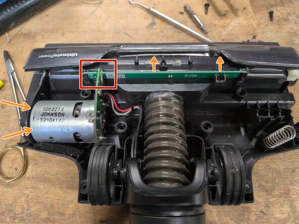
- The floor nozzle was damaged during a repair attempt. The correct procedure for disassembly and reassembly could not be determined exactly. Therefore, only notes are provided here.
- The plug connection between the two circuit boards is extremely delicate. If the housing is opened carelessly, it can break.
- The plastic lever must be UNDER the button on the circuit board during reassembly. This requires a great deal of care during reassembly.
- If necessary, the long circuit board may need to be lifted slightly during reassembly by loosening the motor screws and rotating it slightly. This was not tested.
- The button on the circuit board pulls the gray wire to ground (black). A successful reassembly can be tested this way using a continuity tester.