HP G62-453 Teardown
ID: 27784
Description: Hi everyone, here I am with a new guide...
Steps:
- Remove the 2 panels and the battery at the bottom of the laptop.
- After removing these panels, you'll see the RAM, HDD, and Wi-Fi module.
- Carefully remove the Wi-Fi antennas from the mini Pci-e adapter.
- Note for reassembly: The black antenna attaches to 1 and the gray attaches to 2.
- tip : Make a sketch of the laptop, where all the screws are, and how to put it back afterwards.
- Remove the mini Pci-e Wi-Fi adapter by removing the small screw. Lift the screw side gently, then pull out.
- Now remove the HDD and the RAM
- Remove the HDD by removing the three screws and pulling the Sata connector from the motherboard.
- Remove the RAM by pulling apart the clips on either side of the top stick. The stick should pop up, then pull it out. Repeat for the bottom stick.
- Remove the 6 keyboard screws.
- Remove the DVD drive bay by prying a little spudger between the case and the drive cover. Then gently pull it out.
- The screws should already be removed from the removal of the panel.
- Next, we will remove the screws from the rest of the case.
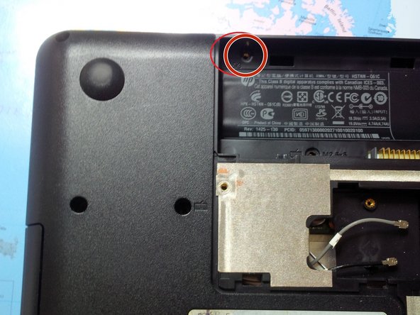
- Start by removing the screws hidden in the battery compartment (M2.5x3).
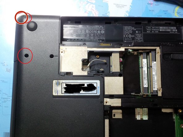
- Now remove the 10 remaining case screws (M2.5x6.5).
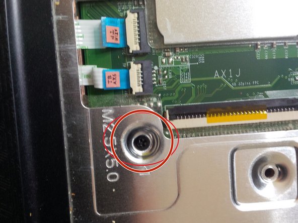
- There are 2 hidden screws in the HDD compartment (see last picture).
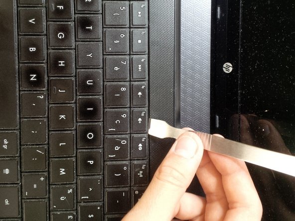
- After removing all the screws, we can remove the keyboard.
- Be careful because you can break keys or the entire keyboard.
- Use a spudger to pry and search for the "locks"
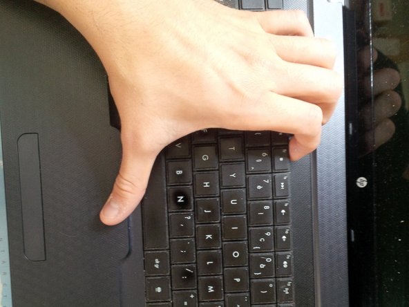
- use your hand to gently remove the keyboard. You will here clicks.
- Be careful for the thin connector under the keyboard.
- open the socket by clicking it up. pull the connector gently away from the socket.
- There are hidden screws under the keyboard. Remove them. (M2.5x6.5)
- remove all the visible connectors.
- the other connectors are from the power button and the mouse pad.
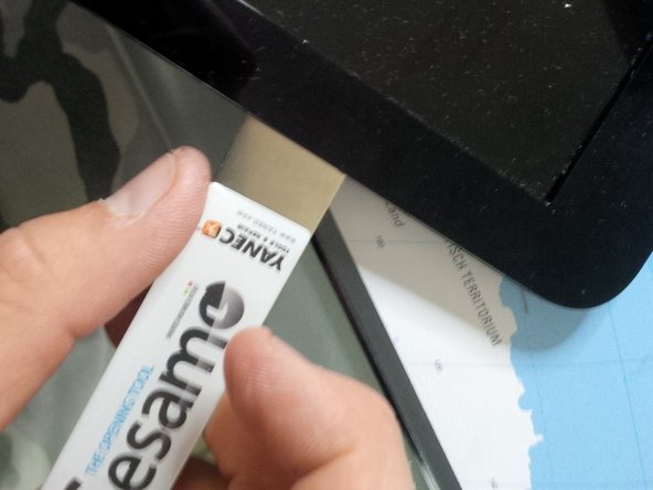
- Now gently remove the case with a spudger and a isesamo opener.
- Gently slide the spudger/opening tool to open the case.
- You will hear clicks.
- be careful for the connectors.
- After you've removed the case you will see the motherboard.
- Remove the screws from the motherboard.
- remove the connectors of the screen.
- be careful with the connector (the bigger of the two.) (With the HP SPARE sticker)
- Remove the sticker ( HP spare) And pull the connector out of the socket.
- if you put back the screen and the connector afterwards , maybe you can tape the LCD cable to the motherboard with electrical tape. It will fit better then and you have less troubles with the screen.
- now we will remove the sata dock from the dvd player.
- like the other connectors , just pull it out the socket. but be gentle.
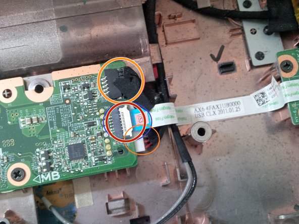
- now remove the usb conncetor + the dc jack connector.
- you can remove the dc jack (head) by pulling it out (sliding). if it's loose, then you can remove the connector from the motherboard.
- if you remove the usb connector, be careful because the cable is taped to the case. pull gently
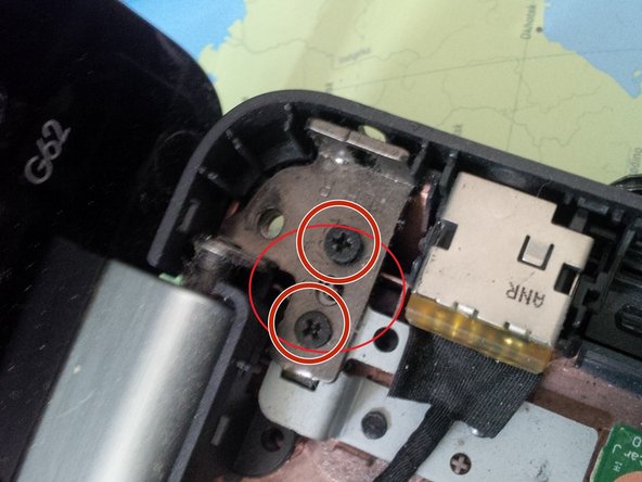
- after removing all the cables/ wires and screws, we can remove the screws from the screen hinges.
- after removing the screws from the hinges, put the entire screen apart.
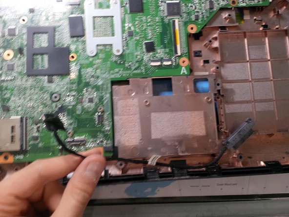
- we will remove the motherboard first. see picture 3. you can remove the motherboard by pulling it up and sliding it to the right.
- if you have to remove the LCD screen connector you have to remove the case arround the screen. same thing if you have a broken screen..
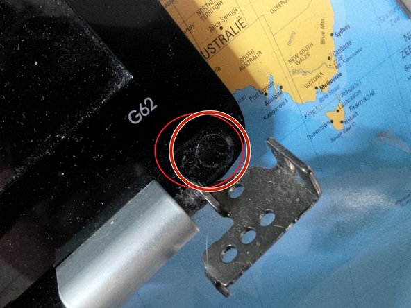
- be carefull if you remove the case around the screen. it's taped to the screen. i removed the case with an spudger. But first remove the 2 screws hidden under a black round sticker at the bottom of the screen, just above the grey hinges.
- after removing the screws , slide the spudger arround the case, you will hear the clicks
- after removing the case. this is the screen internal.
- above you will see the camera, the wifi antenna's . under you'll see the hinges and at the left the lcd connector.
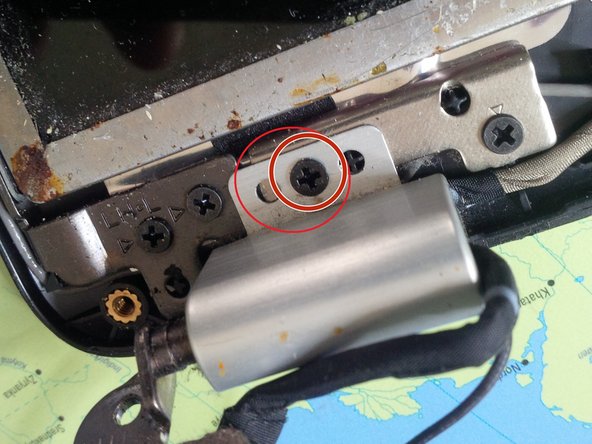
- you can remove the grey plastic caps by removing the screw(s), under the plastic cap you will find the cables running trough..
- you do the same thing at the other side.
- if you remove, or going to remove the screen, be carefull with the cables, most of them are taped to the case or screen.
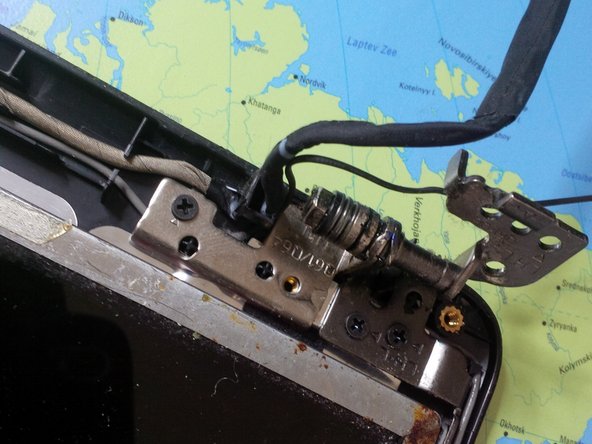
- At the second picture you see the wires after removing the plastic grey cap. if you have problems with screen failure ( like a black screen or bad connection) its best to check this cable first before buying a new one. The wires are sliding to the cap and sometimes they get cut.
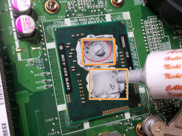
- Now the last steps.. we will put some new coolpaste to the soldered CPU and GPU
- first remove the 4 screws of the cooling socket.
- remove the socket, be carefull for the little power socket attached at the motherboard, running to the cooling fan.
- and than put some drop of cooling paste on the CPU/GPU