Canon PIXMA iP4850 Teardown
ID: 29118
Description: hello all, today we wil take down the canon...
Steps:
- this printer has the well known B200 error.
- we will take the printer apart.
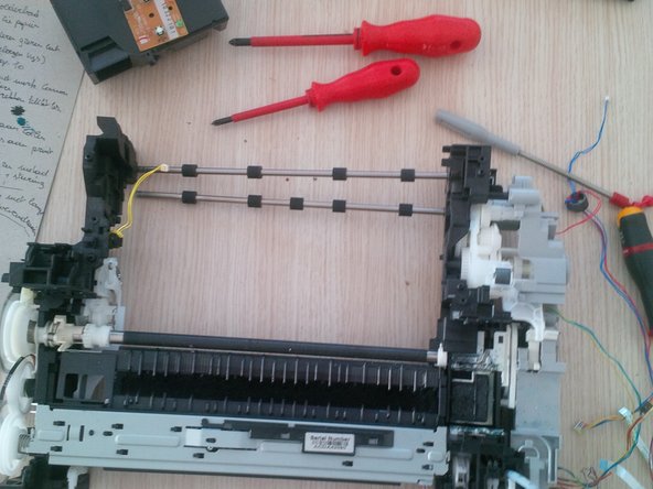
- first step : remove all the loose parts.
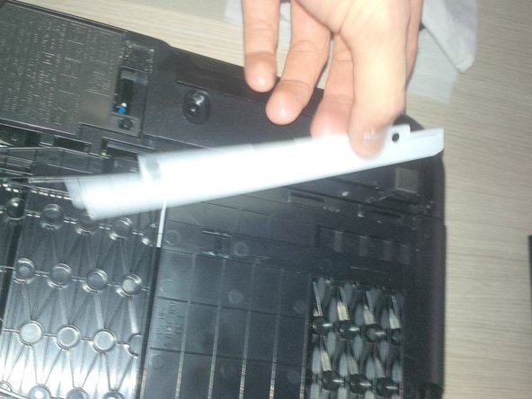
- remove the panel at the back.
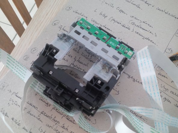
- no we will remove the printhead and the cardridges.
- be carefull with the remaining inkt.
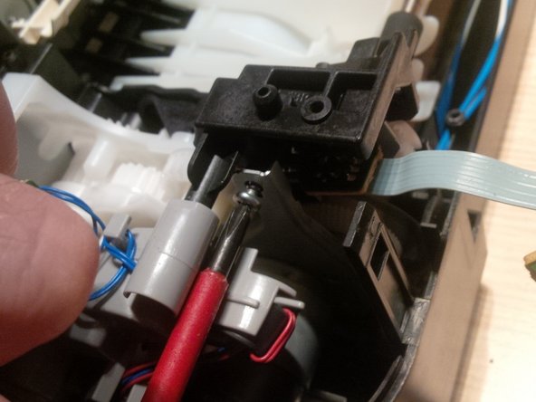
- To remove the printhead you have to plug in the printer again and open up te front panel (like you have to remove the cardridges).
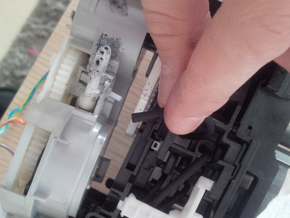
- to remove the printhead you have to pull the levar up (grey) , be carefull its very rough to pull it up.
- remove the printhead, if you only replace the printhead the guide stops here. be carefull for the pcb board, if you only clean the printhead do it carefully. clean it with destilled water, but do not touch the PCB.
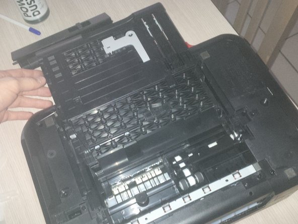
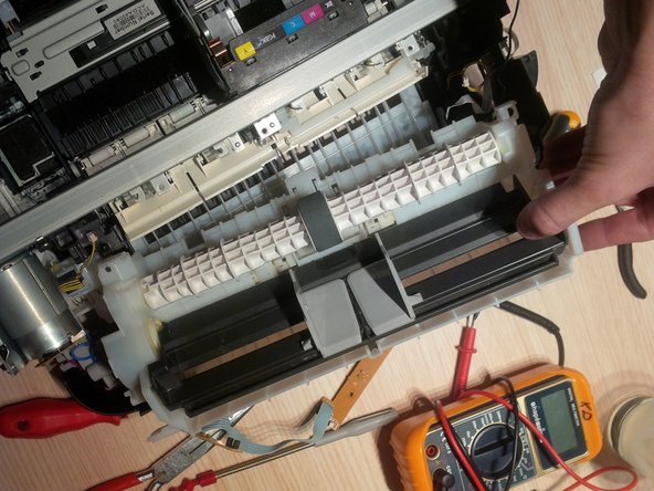
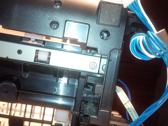
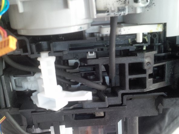
- remove the papertrunk at the botom, see picture 3
- now remove the screws at the white clips.
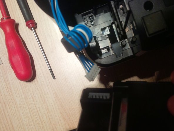
- now we will remove the power supply.
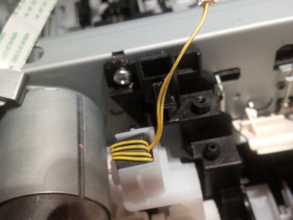
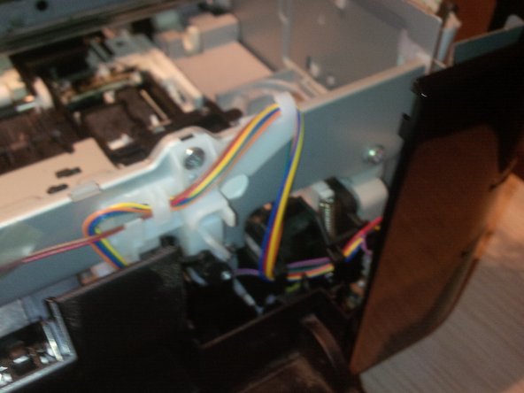
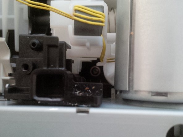
- you'll find clips to loose the power suply . On the picture (number 1) you see how you do it. you'll here the clicks.
- pull the power supply out of the printer, and you will see the white and blue wires. you will see this wires later in the printer again.
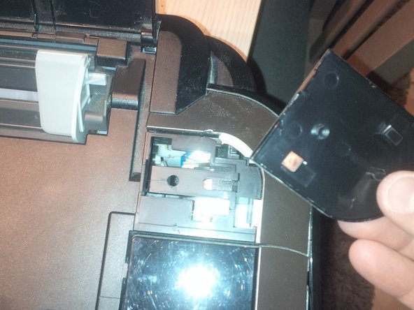
- remove the side panels
- you can remove this by clicking the panel of.
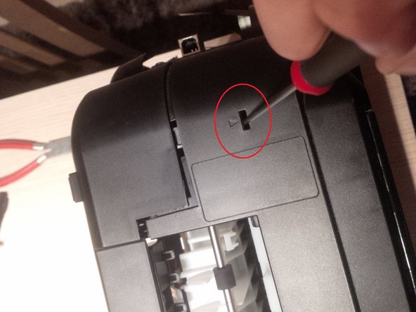
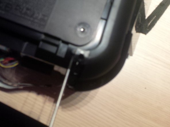
- search for the arrows on the upper deck of the printer. see picture 1
- than click the panel losse at the bottom of the printer.
- again, and i think you know already, it's not so easy to take the printer apart. It's a lot of clicking the panels loose. and sometimes you will think the plastic will brake but it's quite flexible.
- at the left side you'll find the paper drive roll. and at the right side the PCB boards
- remove the upper panel by clicking two clips. at the backside.
- normaly , if my guide is good enough, the printer looks like picture 3 now.
- remove the printer paper roll
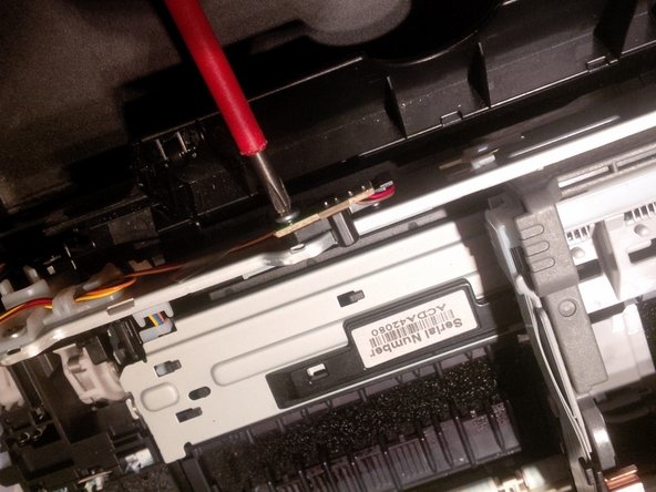
- remove the red circled screws.
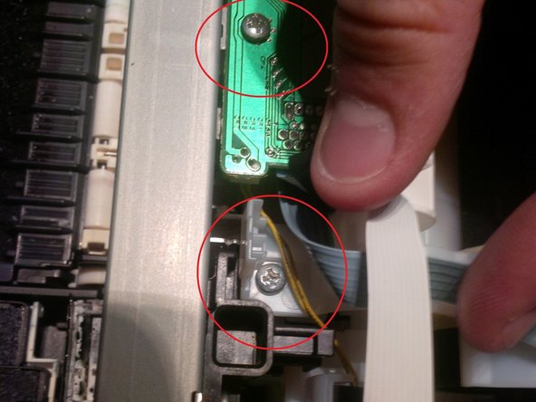
- this step and the next is actualy 1 big step.
- remove the 2 screws. one on a PCB board and the other in the white plastic.
- remove the long PCB , remove the three thick screws
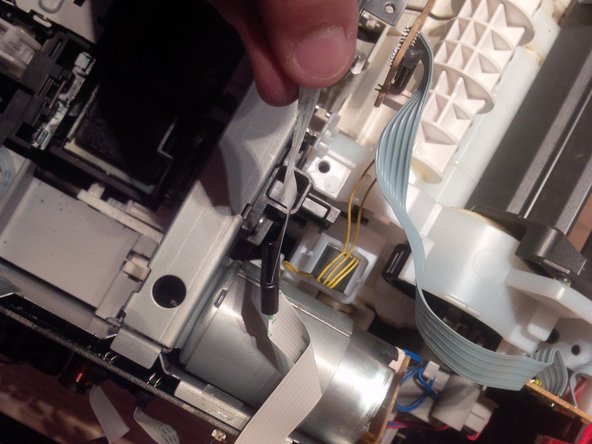
- remove all the wires, some are attached to the PCB.
- now you can remove the paper roll.
- remove the other visible scerws at the back.
- same as before, remove all other visible screws at the side.
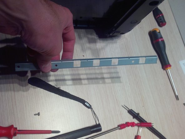
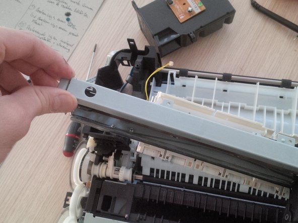
- now remove the metal plate (long) , 4 screws in total. 1 screw is attached at an PCB board.
- the pictures here are to remove the other metal plate, you'll see the colored wires running trough. remove the plastic and metal frame
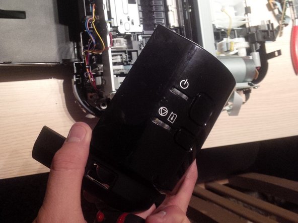
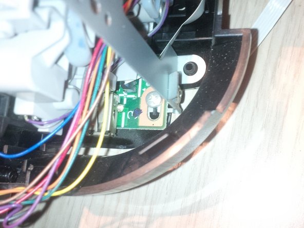
- in this step we will remove the panel and PCB of the power button.
- remove the visible screws and pull the plastic frame off.
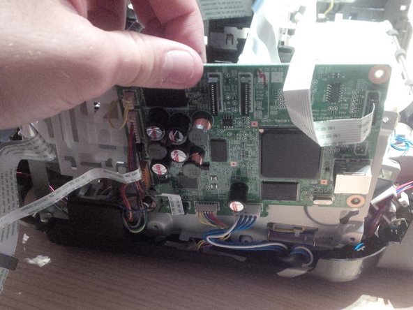
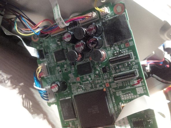
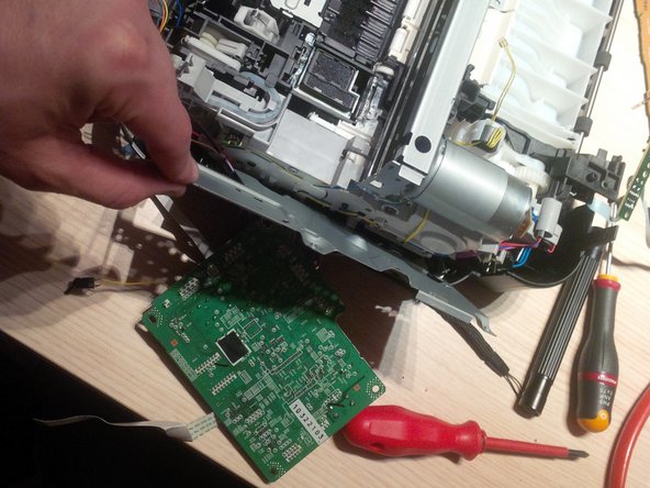
- remove the main PCB board.
- remind were al the wires run to. i made a plan of it so i could use it later in an other printer.
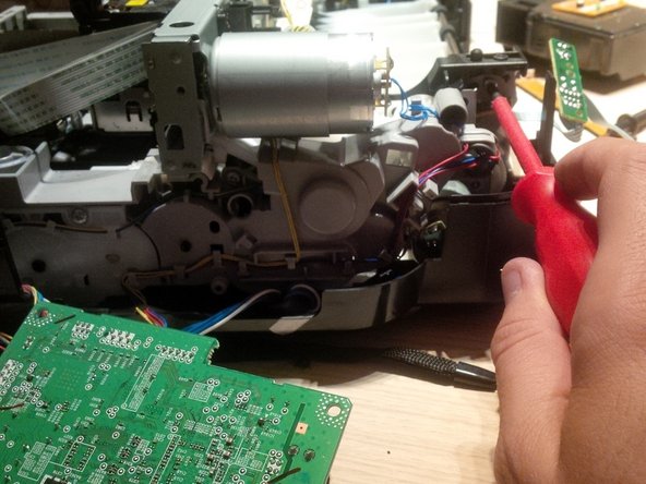
- remove the metal plate and screw behind the PCB board
- remove the plate and remove the hidden screws
- remove all other screws
- remove the metal plate ( where the printhead cable runs trough)
- remove the last screws from the bottom plate
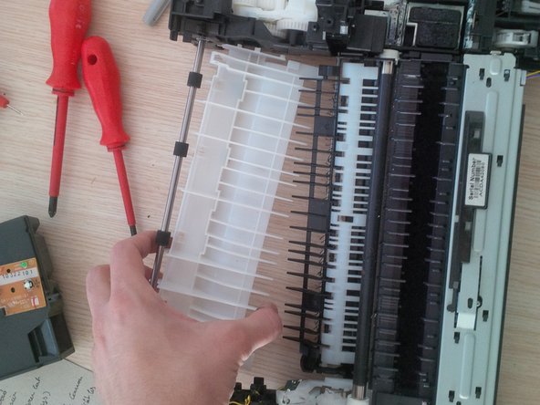
- remove the white plastic plate like you see on the pictures
- remove the plastic rotors.
- gently remove the ink tubes.
- there is still inkt left in the tubes so use cotton towels or tissues.
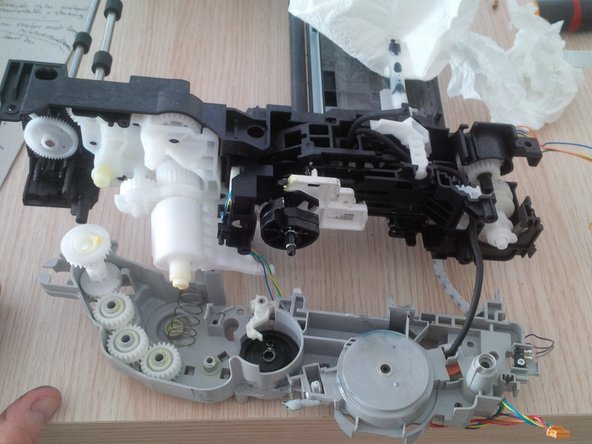
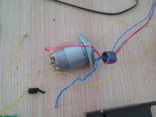
- in the last pictures you will see all the parts like the motor PCB boards, power button print head holder ...
- hope this guide helped you out.