BlackBerry PlayBook Front Panel Replacement
ID: 31783
Description:
Steps:
- Use a plastic opening tool to pry the back panel off by inserting it in between the front and back panel.
- There are clips that need to be released on all four sides of the device.
- When replacing the back cover insert the bottom side first ( usb and hdmi ports stick out about 2mm ) inserting them into the covers openings will allow for easier reassembly
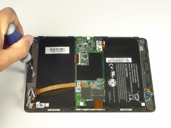
- Remove 1.55x.33mm Phillips screw from the metal frame.
- Remove 1.5x4.25mm Phillips screw from speaker bar.
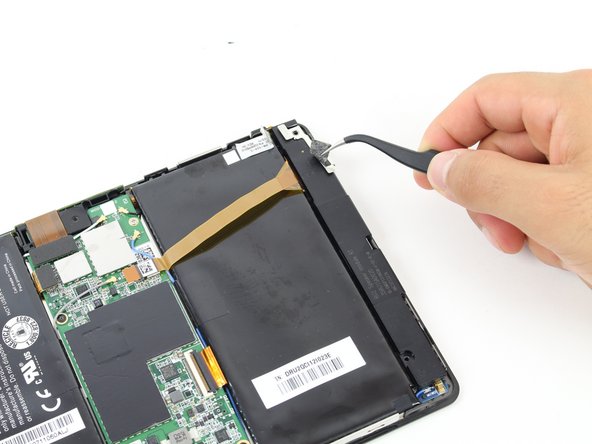
- Peel off the stickers holding the left speaker in place with a tweezer or by using your fingers
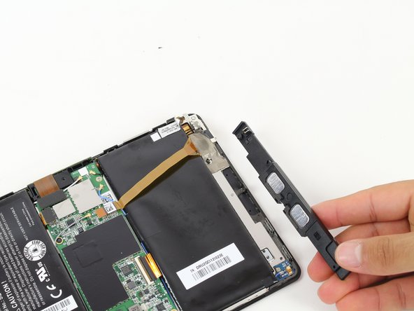
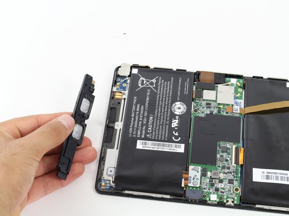
- Slide the left speaker bar out from its metal bracket.
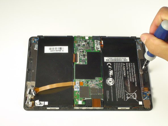
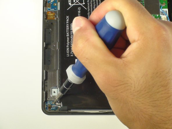
- Remove both 1.5x4.25mm Phillips screws from the right speaker bar by using the Phillips Screwdriver.
- Lift the right speaker bar to remove it.
- Remove the battery connector using either your fingers or a pair of tweezers.
- Unscrew two 1.17x2.9mm Phillips screws from the white connector port.
- Lift the battery connector away from the motherboard using a spudger.
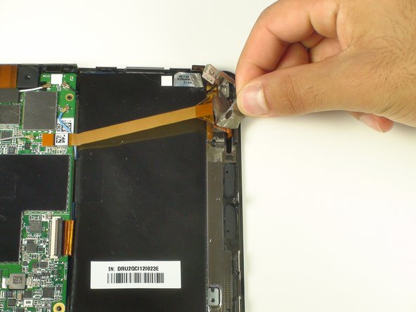
- Remove the flat-top connector coming from across the camera assembly with a spudger.
- With the spudger, remove the flat-top connector coming from underneath the motherboard.
- Remove the clipped ZIF data connector coming from underneath the motherboard.
- Lift up the black plastic clip with a spudger.
- Pull the connector out gently using tweezers.
- Be careful to ensure that the black plastic clip has been lifted away from the connector ribbon before pulling on the connector. The clip should be loose and easy to wiggle. Removing the connector before it is unclipped can cause damage.
- Remove the following five screws from the motherboard.
- Three 1.5x2.5mm Phillips screws
- Two 1.55x2.38mm Phillips screws
- Lift all four antenna connectors from the motherboard again using the spudger.
- Gently lift the motherboard away from the device. If there is any resistance, check the previous steps to ensure that all connections have been removed.
- Remove both screws attaching the metal mid-frame to the front panel.
- Two Phillips screws
- Unscrew the small blue boards in each corner with the same Phillips screwdriver.
- Remove the sticker holding the touchscreen controller in place to free it from the mid-frame.
- Unclip all attachments along the sides of the tablet.
- Two large clips on the top of the device.
- Four medium clips on the bottom of the device.
- One small clip on the side of the device, near the headphone jack.
- This last clip is particularly difficult and might require a sharper tool to remove.
- Gently lift the metal mid-frame away from the front panel.
- A connector runs through a hole in the mid-frame under the area where the motherboard used to rest. While lifting, ensure that this connector is properly fed through the hole.
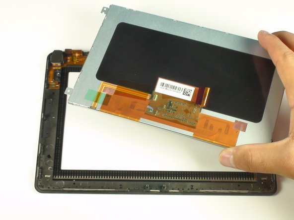
- Remove the one remaining Phillips screw holding the display in place.
- Gently lift the display out of place.