Sony CFD-8 Main Circuit Board Replacement
ID: 31829
Description: This guide explains how to remove and replace...
Steps:
- Remove the battery cover on the back of the boombox by applying downward pressure to the two clamps.
- Be sure to unplug the boombox from the wall before attempting to open it for repair.
- Push against the positive end of each battery. Once it is loose, lift the battery out. Repeat for all six batteries.
- The top row of batteries have the positive side pointing right. The bottom row of batteries have the positive side pointing left.
- Hold the boombox handle at an angle to access the screws behind the CD player.
- Use a Phillips #1 screwdriver to unscrew the top two 14 mm screws. You may need a flashlight to see the screws.
- Remove four 14 mm screws using a Phillips #1 screwdriver. Two of these screws are at the bottom of the boombox and the other two are on either side of the boombox as highlighted in the related images.
- All four screws have black arrows (not visible in the photo) indicating their location on the boombox.
- Gently separate the front panel from the back panel.
- Remove the two connections holding the front panel to boombox.
- One connection is located on the upper left hand side of the main circuit board.
- The other is a large white strip slightly to the right of the cassette player.
- Do not touch the cylindrical parts on the circuit board. These are capacitors and may deliver a shock!
- Remove the front panel.
- Use a Phillips #1 screwdriver to unscrew the four 12 mm screws that connect the cassette motor to the brackets.
- Wiggle the cassette motor to remove it from the two brackets. Do not remove the motor completely, only separate the motor from the two brackets.
- Remove the two wire sets that connect the cassette motor to the main circuit board. Then gently remove the motor.
- Use a Phillips #1 screwdriver to unscrew the four 12 mm screws that connect the brackets to the main circuit board.
- Gently pull the brackets outwards to remove them.
- Use a Phillips #1 screwdriver to unscrew the 10 mm screw located on the top left of the tuner wheel bracket. Remove the metal bracket.
- Use a Phillips #0 screwdriver to unscrew the 6 mm screw in the center of the tuner wheel. Remove the tuner wheel carefully.
- The tuner wheel slightly protrudes out of the top of the boombox. Be mindful of this when removing tuner wheel.
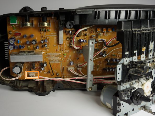
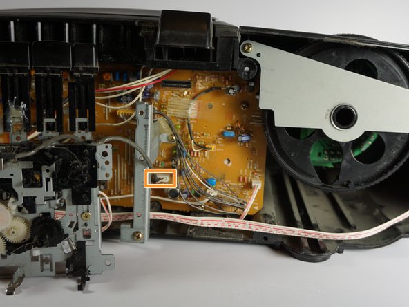
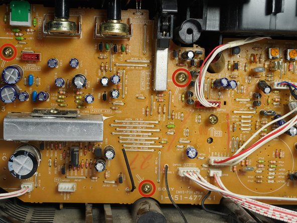
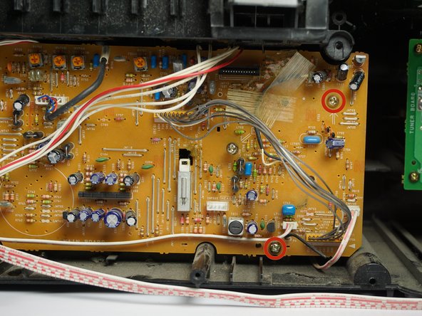
- Use a Phillips #1 screwdriver to unscrew the five 10 mm screws located on the main circuit board.
- Note that the second picture depicts the left half of the main circuit board. The third picture contains the right half.
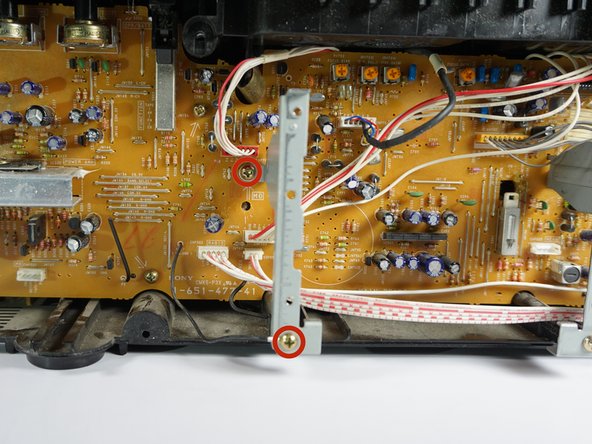
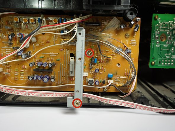
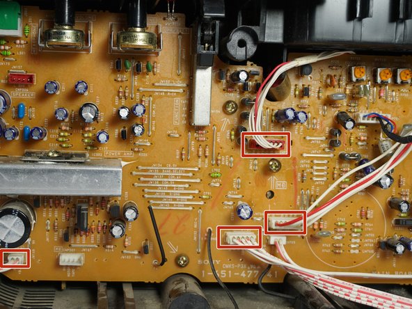
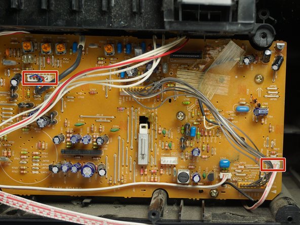
- Disconnect the six wire sets that connect to the main circuit board as shown. Each of the wires have 3-6 prongs.
- The order of removal is not important.
- Note that the second picture depicts the left half of the main circuit board. The third picture contains the right half.
- The connections for each of these wire sets is a different size. When reassembling, use these size differences to determine how the wire sets reconnect to the circuit board.
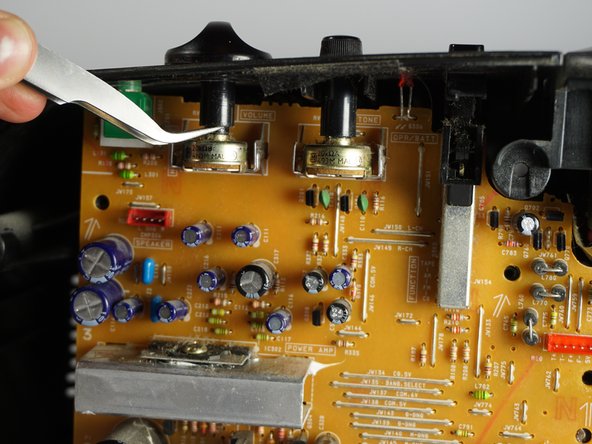
- Use a pair of tweezers to pry off the volume and tuner buttons located on the top left of the boombox.
- Pry the buttons off by placing the tweezers under each button as shown in the first picture. Proceed to push gently upwards until the button pops off.
- Gently wiggle and pull the main circuit board outwards until it is fully removed.
- Ensure that the mode tuner on the top left of the circuit board is not blocked by the tuner wheel attached to the case. Sometimes the tuner wheel will obstruct the circuit board during removal.