Toshiba Excite 10 AT300 Headphone Jack Replacement
ID: 31919
Description: This guide illustrates the steps required to...
Steps:
- Remove the SD card from the SD card slot.
- Use the opening tool to separate the front and rear panels by slipping the tool underneath the screen edge and sliding it around the entire device.
- Make sure you unclip all of the clips on the back panel, or pulling it off will be difficult and may damage the tablet.
- Remove the speaker cable from its socket by gripping both sides of the white connector piece with tweezers and pulling straight out.
- Be careful not to rip the wires out of the white connector piece.
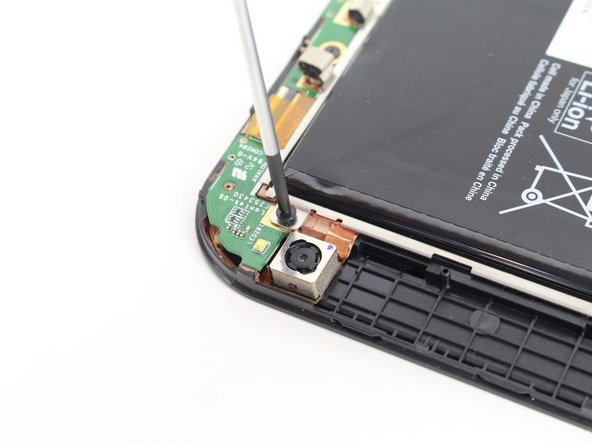
- Using a #00 Phillips screwdriver, remove the following screws:
- Five 3mm Phillips #00 screws
- Gently lift the battery, pulling away from the tab holding it in place at the bottom.
- While holding the battery up, use a pair of tweezers to remove the battery cable from its connector.
- Using a #00 Phillips screwdriver, remove the following screws:
- Five 3mm #00 Phillips screws
- Remove 4 pieces of orange tape with either your hands or using tweezers.
- Using the spudger, lift up the white portion of ribbon cable's housing.
- Using either your hands or tweezers, gently separate the four ribbon cables from black portion of the housing.
- The top left ribbon cable in the first photo is taken off by lifting the black portion of the housing instead of the white portion.
- Be careful not to bend the ribbon cables as any damage may result in the device not functioning properly.
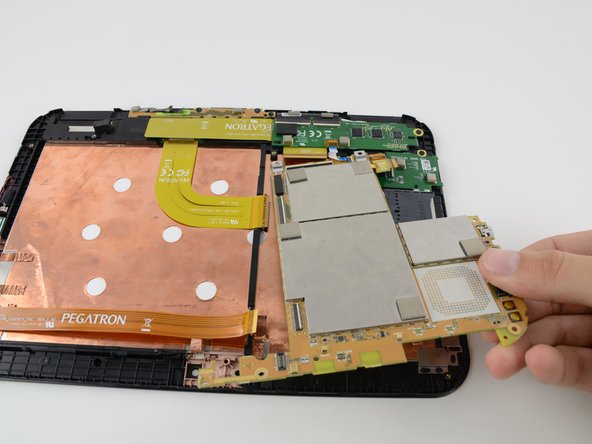
- Using your hands gently lift circuit board from device housing.
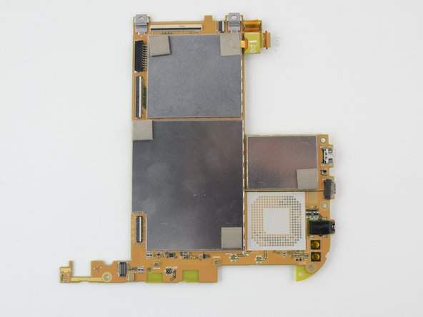
- Be extremely careful with the removed circuit board. It contains fragile components that if damaged may result in the device not functioning properly.
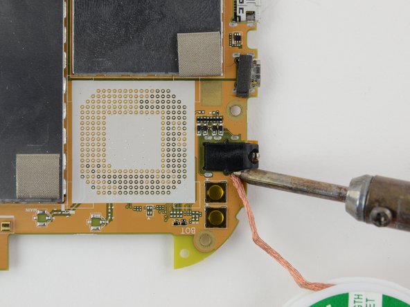
- Using a soldering iron and desoldering braid, remove the solder from the 5 terminals connecting headphone jack to circuit board.
- Replace the broken headphone jack the with new one. Using the soldering iron, solder the jack to the same five terminals that connected the old headphone jack to the circuit board.