Apple Airport Extreme Model A1408 Antenna Replacement
ID: 32040
Description: This guide will cover how to safely remove the...
Steps:
- CAUTION: The heat gun and hair dryer can get very hot. Do not put your hands or any other body part too close to either device. Also, do not touch the back pad right after heating it.
- Use a blow dryer or heat gun on a medium to high heat setting on the back pad to loosen the glue that attaches it to the device.
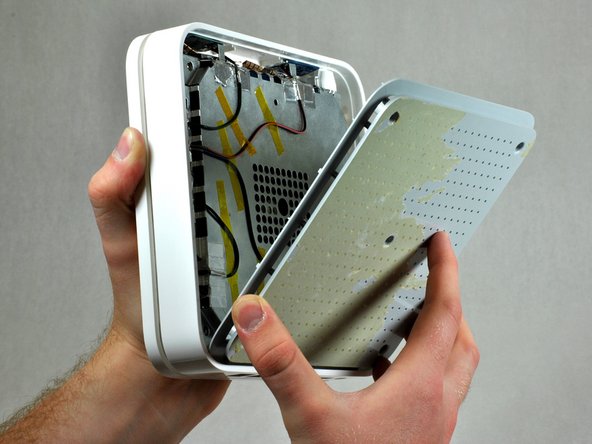
- To avoid ripping the back pad, gently peel it back from one corner until the pad is completely off.
- Use heat in areas where the glue is not loose enough.
- You may need to reattach the back pad with double-sided tape if the glue is not tacky enough to stick the pad back on.
- After removing the back pad, unscrew the five 5 mm Phillips #00 screws in the large, deep holes in the plastic casing. The plastic casing should come off easily after removing all the screws.
- When installing the plastic back cover, ensure the lip is aligned with the ports on the back of the device.
- Insert a narrow plastic opening tool into one of the notches. Apply moderate force to pull the metal casing from the plastic outer casing. You can use the rim of the outer case as leverage. You should hear a click when the metal casing detaches.
- After you hear the click, remove the inner metal case from the outer case using your hands. It should not take very much force.
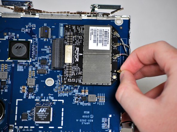
- Remove the four wires coming from the antennas by pinching the cable at the tip and gently pulling up on it until it pops out of the socket.
- Repeat for the remaining three wires.
- You might need to wiggle the wire to free it from the socket.
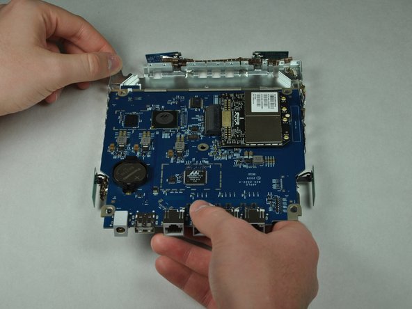
- Separate the logic board from the inner metal casing by gently pushing up on the logic board from the bottom while holding down the casing edges.
- Pull the logic board away from the metal casing to separate the two.
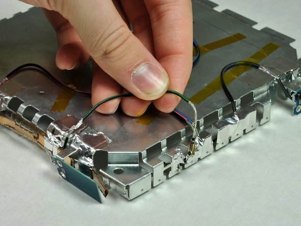
- The four antennae are located here. Select the one you are replacing.
- Remove the 5 mm Phillips #00 screw holding the blue antenna to the logic board.
- Remove the tape that attaches the wire to the logic board.
- Lift wire out of its port. You should have one free end now.
- Finish by lifting the antenna out of its position. The antenna and wire should be free from the logic board at this time and ready for replacement.