Samsung Galaxy Attain 4G Front Camera Replacement
ID: 34818
Description:
Steps:
- Begin by turn the device over to it's back, with the screen facing down.
- At the top of the device there is a small notch that is used to remove the battery door.
- Using a pry tool or your fingernail, pry off the battery door from the main housing.
- Place the battery door to the side.
- Using a pry tool or your fingernail, pry the battery up towards you.
- You have now removed the battery!
- Make sure when replacing the battery that the arrow on the bottom is facing down.
- Remove the 6 Phillips head screws that hold the rear housing in place.
- Using a spudger or plastic pry tool, slowly go around the phone between the display & rear housing to release the clips.
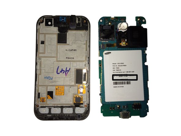
- Lift the rear housing from the display assembly.
- Using your spudger/plastic pry tool, disconnect the headphone jack flex cable.
- Using your spudger/plastic pry tool, disconnect the rear speaker flex cable.
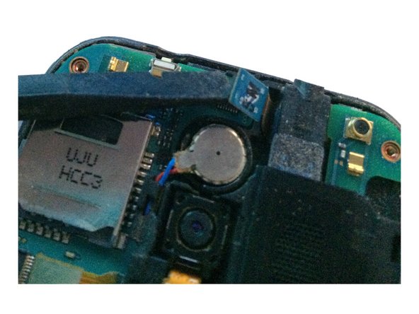
- Using a spudger/pry tool, carefully remove the vibration motor from its housing. This has a mild adhesive on the bottom.
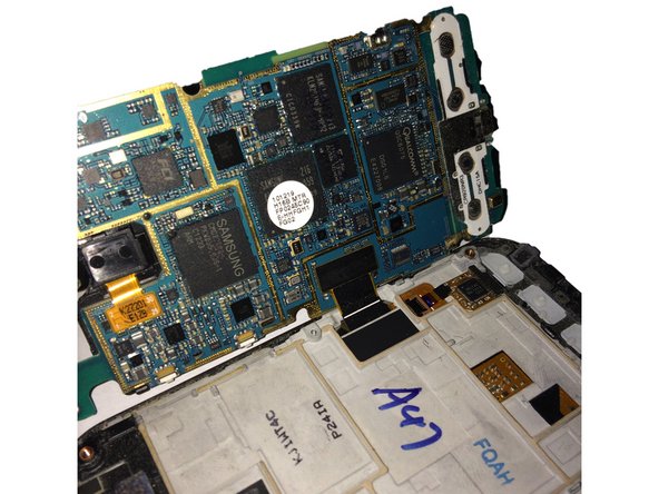
- After removing both flex cables, slowly move the logic board to the left of the screen assembly.
- Do not try and remove the logic board all the way, as you still have to remove the display assembly flex cable!
- Using your spudger/plastic pry tool, disconnect the LCD/Digitizer flex cable.
- You have now removed the logic board from the display assembly.
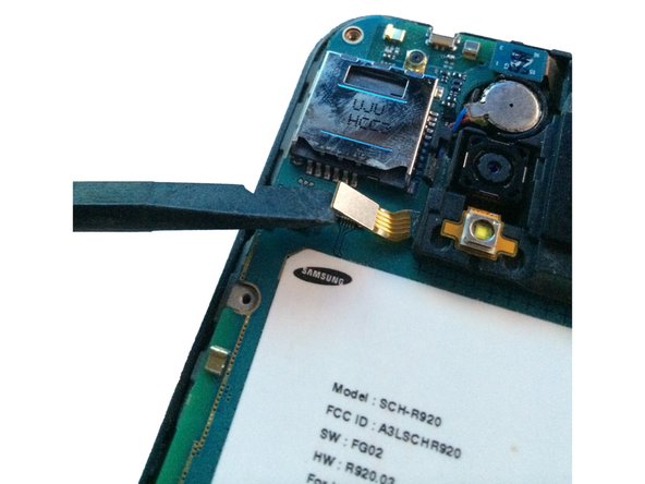
- Using a spudger/plastic pry tool lift the brown ZIF tab on the front-facing camera connector.
- Do not pry at the black part, as this will damage the connector on the board.
- Carefully pull the camera out of it's connector and set to the side.