Volume Control Potentiometer Cleaning
ID: 35081
Description: Read me: Before attempting this repair, read th...
Steps:
- In order to ensure there is no residual power, unplug the receiver for 48-72 hours. This will drain the capacitors so it can be safely serviced.
- Before working on the unit, disconnect the unit from the wall. Hold the power button in for 60 seconds to drain the capacitors.
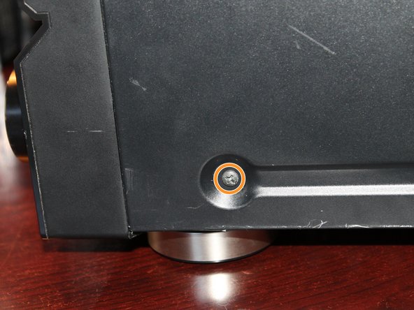
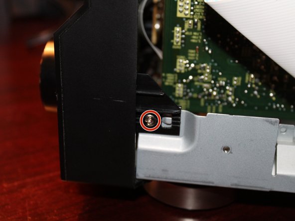
- If present, remove this screw. This was not in my unit, but may be in yours.
- Remove the two Phillps screws holding the faceplate on the receiver. Sort these individually as they are different.
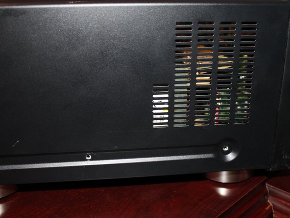
- Remove the 2 Phillips #2 screws from the left side of the receiver. They are the same length.
- Remove the 1 screw on the right side of the receiver, it is the same bit size as the previous screws. While it appears to be the same, sort it separately.
- Exercise extreme caution with the receiver at this point! You will not be protected from socks if you touch a charged component!
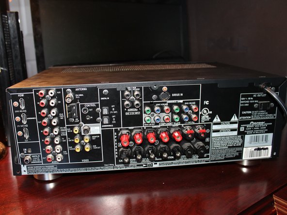
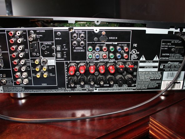
- Remove the 3 Phillips #2 screws from the back of the receiver. Once these are removed, the cover will come off.
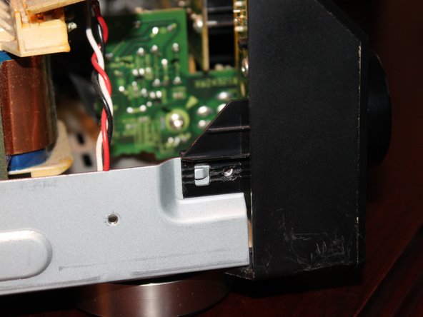
- If the clip in the faceplate is missing, the unit has been previously serviced. It is not essential, but try to keep it intact as the bezel will be loose without it.
- This pin is installed by the factory. To remove this pin, push it out from the back until it is loose. Remove the pin when it is loose.
- After the faceplate pin is removed, remove the 2 Phillips #2 screws that hold it to the chassis. Both screws are the same length.
- First time removal can be tricky. Work slowly on an unserviced receiver.
- Remove the control knob from the receiver. To do this, pull the knob off firmly. Too much pressure may result in a broken knob and potentiometer.
- Special attention to the front panel is required with iPod Direct models.
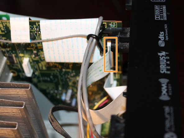
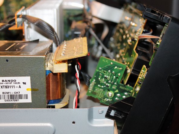
- iPod Direct: Disconnect the wire that plugs into the board as shown in the 1st picture. The board will need to be removed as well.
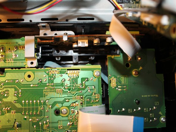
- Disconnect the flatflex that connects the front panel display to the rest of the receiver.
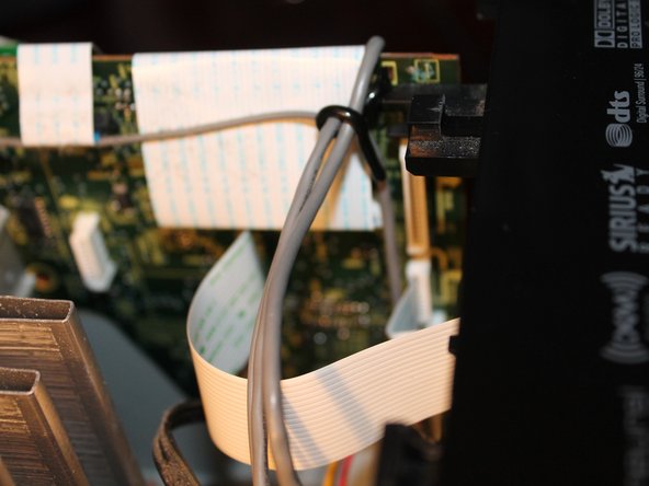
- Once the unit is reassembled, these zipties must be replaced. Failure to do this will result in protection mode errors.
- Cut the zipties that hold the front panel wires on the fan. This provides better component access.
- With the faceplate loose and all of the cables disconnected, unclip the faceplate one side at a time. Lay the faceplate flat on your workspace. Leave enough room to access the boards on the front panel.
- iPod Direct: Remove all 4 Phillips #1 screws. Remove the support bracket and PCB.
- Non iPod Direct: Remove the Green and Red screws. No additional screws need to be removed.
- WARNING: This screw is unique and has a different thrad. Sort it separately.
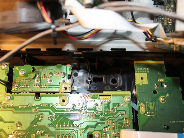
- Remove the 3 Phillips #2 screws that hold the volume control board in the receiver's front faceplate.
- A little contact cleaner goes a long way. If you need to use more then 1-2 sprays, a replacement board may be required.
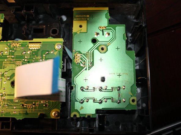
- With the control board loose from the front panel, spray contact cleaner into the potentiometer. Clean up any excess contact cleaner once you are done.
- This fix may not be permanent and the problem may come back. Replace the board or potentiometer if this happens. Let the switch dry for 1 hour before reassembly.
- If you do not have zipties available, tuck the wires in the fan so that they cannot easily move. This can be used as a short term solution.
- Wipe off any excess contact cleaner on the PCB. Reinstall the board once the contact cleaner is dry.