iHome iH9 Volume/Tuning Dials Replacement
ID: 37780
Description: Is your device's dial sticking or not rotating...
Steps:
- Pull the tab towards you and lift up to remove the battery cover.
- Remove the two AA batteries.
- Unscrew the four 8mm Phillips #2 screws.
- Unscrew the six 25mm Phillips #2 screws.
- Reinstall the backup battery cover so it is out of the way.
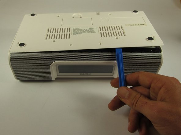
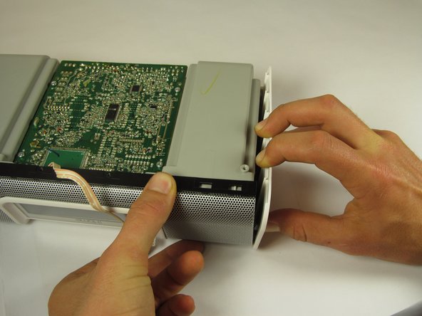
- Pry the backplate up with a plastic opening tool between the back plate and the speaker grill.
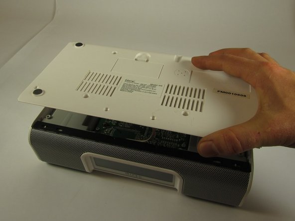
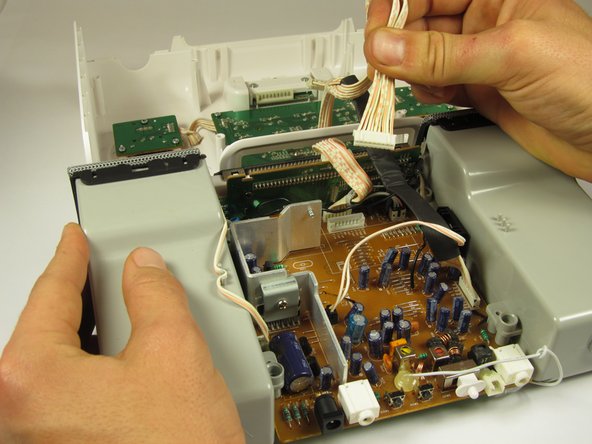
- Be careful when lifting the bottom plate up; there is a short white and orange 4-pin connector attached to its underside.
- Lift the bottom plate up while making sure the connector remains attached.
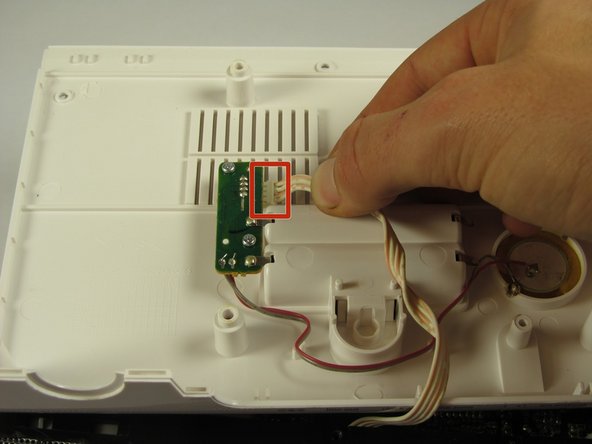
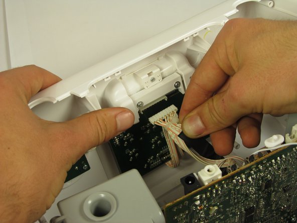
- Use your hands to flip the backing plate away from you and rest it upside down on the iH9.
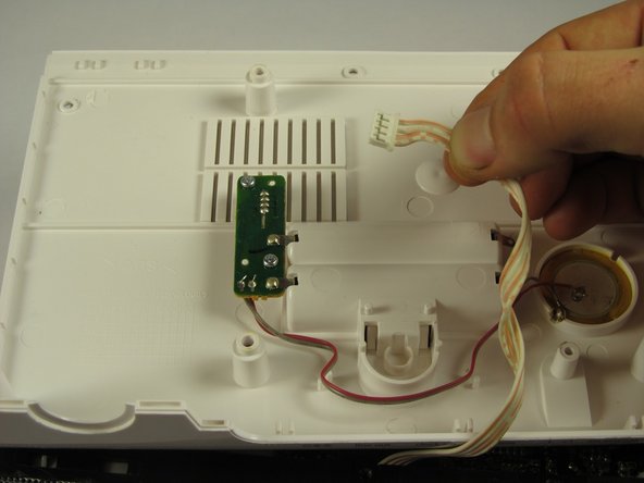
- Unplug the white and orange 4-pin connector by pulling it in the direction of the wires.
- Set the backing plate aside.
- Place the device so that the speaker grill is face down.
- Remove the two 10mm Phillips #2 screws on interior sides of the speaker housings.
- Place the iH9 upside down.
- Wires connect the core assembly to the housing; do not attempt to pull the core assembly completely out.
- Using both hands, pull the housing siding away from the device while simultaneously lifting the motherboard and speaker assembly straight up.
- Repeat for the other side.
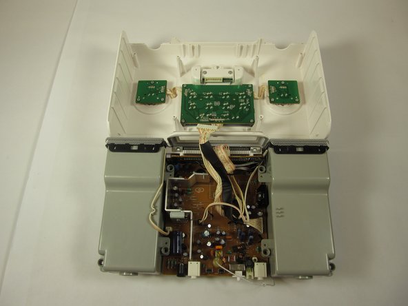
- Stand the iH9 on its grill.
- Separate the motherboard and speaker assembly by rocking it back and forth and pulling the assembly towards you.
- Remove the small back panel.
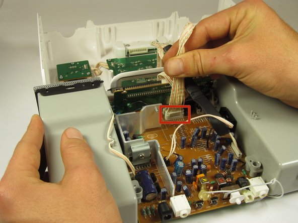
- Firmly pull the wide 9-pin connector with black covering on the underside of the upper housing to unplug it.
- Lay the housing and core assembly flat and close to each one another.
- Unplug the narrow 9-pin connector from the motherboard.
- Cut the zip tie holding the wires together with a wire cutter. The two sides of the device housing are now fully separated.
- Take the top cover off and flip it so the buttons are face down.
- Remove the three 8mm Phillips #0 screws on the back of the dial circuit board.
- Use one hand to tilt the front edge of the cover up.
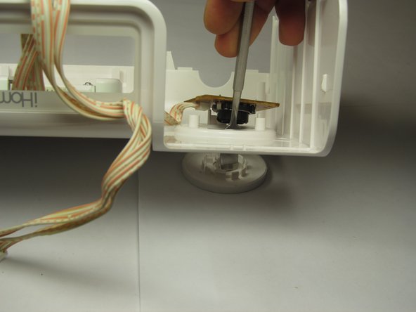
- Use the other hand to rotate the dial from underneath until you see one of larger tabs on the back side of the dial.
- There are two large tabs which are located on opposite sides of the dial, between the circuit board and the cover.
- Use the nylon or metal spudger tool to push one of these larger tabs inward.
- After pressing tab inward, forcefully push down on back of dial.
- Pushing down will pop the whole circuit board, button, and dial assembly apart.