MacBook Air 13" Early 2015 I/O Board Replacement
ID: 40695
Description: Use this guide to replace the I/O board,...
Steps:
- Before proceeding, power down your MacBook. Close the display and lay it on a soft surface, top-side down.
- Use a P5 Pentalobe driver to remove ten screws securing the lower case, of the following lengths:
- Two 9 mm screws
- Eight 2.6 mm screws
- Wedge your fingers between the display and the lower case and pull upward to pop the lower case off the Air.
- Remove the lower case and set it aside.
- To ensure that everything is de-energized and won't turn on while you're working, it is recommended that you disconnect the battery.
- Grab the clear plastic pull tab attached to the battery connector and pull it parallel to the board toward the front edge of the Air.
- Do not lift upward on the connector as you disconnect it or you risk damage to the connector socket.
- Use the flat end of a spudger to pry the I/O board cable connector up out of its socket on the I/O board.
- Carefully peel the I/O board cable from the adhesive securing it to the top of the fan.
- During reassembly, make sure this cable is in the correct orientation. It will fit if reversed, but the laptop will not boot.
- The following connector has an especially deep socket. Use care when disconnecting it.
- While gently pulling the I/O board cable upward near its connection to the logic board, use the flat end of a spudger to pry up on alternating sides of the connector to help "walk" it out of its socket.
- Remove the I/O board cable.
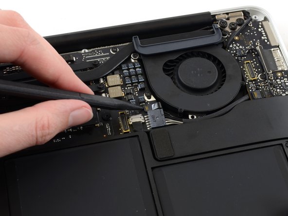
- Use the tip of a spudger to carefully flip up the retaining flap on the fan cable ZIF socket.
- Be sure you are prying up on the hinged retaining flap, not the socket itself.
- Peel the rubber gasket off the adhesive on the top of the fan.
- Remove the following three screws securing the fan to the upper case:
- One 5.2 mm T5 Torx screw
- One 3.3 mm T5 Torx screw
- One 4.4 mm T5 Torx screw with a short head
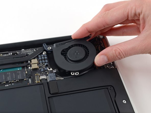
- Lift the fan from the I/O board side and pull it free from the upper case.
- Removing the fan will also disconnect the fan ribbon cable. Be careful not to snag it.
- Disconnect the I/O board by pulling its power cable away from its socket on the logic board.
- Pull the cable parallel to the face of the logic board toward the right edge of the Air.
- Use the flat end of a spudger to pry the left speaker cable connector up and out of its socket on the I/O board.
- Pry up from beneath the wires.
- Use the tip of a spudger to carefully flip up the retaining flap on the microphone ribbon cable ZIF socket.
- Make sure you are flipping up the retaining flap, not the socket itself.
- Remove the single 4.1 mm T5 Torx screw securing the I/O board to the upper case.
- Gently de-route the camera cable from its notch on the I/O board and push it out of the way with the tip of a spudger.
- Lift the I/O board from the logic board side and pull it free from the upper case.
- Removing the I/O board will also disconnect the microphone ribbon cable. Be careful not to snag it.