Envizen V100M LCD Screen Replacement
ID: 40779
Description:
Steps:
- Remove the two screws on the side of the tablet that hold the back cover in place using the ifixit PH00 screwdriver.
- The two screws for the back cover are: 1.5mm diameter x 3.5mm long
- Pry along the edge of the device to separate the back cover from the device.
- The speakers are attached to the back cover and motherboard assembly so remove carefully.
- Remove the non-conductive tape located on the battery and motherboard assembly.
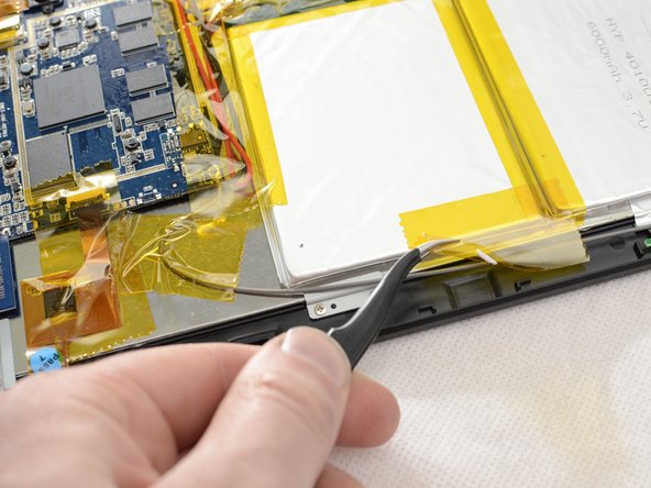
- Slide the ifixit spudger under the battery, and work down the side of the battery, releasing it from the adhesive holding it down.
- Remove battery from the Envizen V100M.
- Remove the solder from the red and black wires from the battery attached to the motherboard. Here is a guide on how to solder.
- Remove the red and black wire from the motherboard using tweezers. If tweezers are unable to remove the wires, heat can be used to loosen the solder allowing for the wires to be removed.
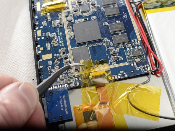
- Remove the black and white wires from the motherboard. These wires power the LCD screen. Remove the black and white wires by first trying tweezers and if difficult use heat to loosen the solder allowing for the removal of the wires.
- Note during final installation remember to match the location of the black and white wires to the picture
- Remove the five screws holding the motherboard assembly down using the ifixit PH00 screwdriver
- These screws are also 1.5mm in diameter and 3.5mm long
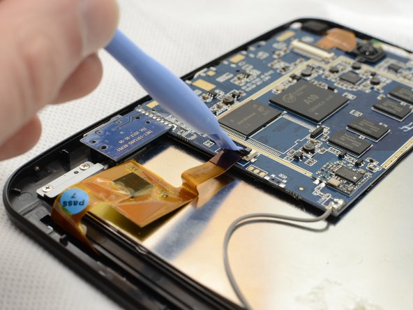
- Remove the three ribbon cables from their couplings.
- Using the prying tool gently push the bracket up, allowing for the cable to right out.
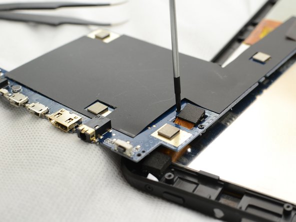
- Remove the solder holding the white ribbon cable in place, here is a guide on how to solder.
- Then flip the motherboard over to access the screws for the rear facing camera.
- Be very careful that you doe not tear the wires for the camera. gently flip the motherboard making sure to not stress out the wires.
- Unscrew the camera from the back of the motherboard using the ifixt PH00 screwdriver.
- Gently push on the black plastic bracket holding the camera in place. The bracket should pop right out.
- The screws for mounting bracket are also 1.5mm diameter and 3.5mm long.
- Now the motherboard is completely removed from the tablet.
- Place the motherboard in a static-free location
- Remove the three ribbon cables from their couplings
- Using the prying tool gently push the bracket up, allowing for the cable to right out.
- Remove the solder holding the white ribbon cable in place, here is a guide on how to solder.
- Then flip the motherboard over to access the screws for the rear facing camera.
- Be very careful that you doe not tear the wires for the camera. gently flip the motherboard making sure to not stress out the wires.
- Unscrew the camera from the back of the motherboard using the ifixt PH00 screwdriver.
- Gently push on the black plastic bracket holding the camera in place. The bracket should pop right out.
- The camera is then free from the motherboard assembly and can be replaced.
- The screws for mounting bracket are also 1.5mm diameter and 3.5mm long.
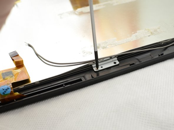
- Remove the six brackets around the outside of the LCD screen using the ifixit PH00 screwdriver
- The 12 screws holding down the mounting brackets are 1.5mm in diameter and 2.8mm long
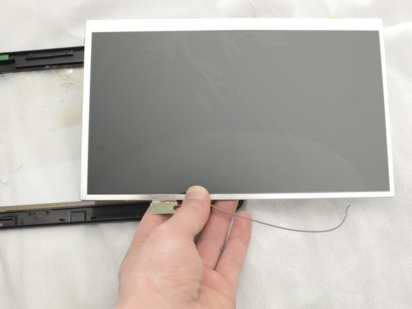
- The LCD can now be removed from the plastic tablet housing.