Nutone IM-5006 Intercom Main Circuit Board Power Supply Capacitor Replacement
ID: 47574
Description: This guide outlines how to replace capacitors o...
Steps:
- Remove all power to the intercom by tripping the appropriate circuit breaker.
- Remove the 4 corner screws holding the intercom in its mounting bracket.
- Tip the intercom down. It is hinged at the bottom.
- Take photos of where each wire from the wall attaches to the intercom.
- When removing the wires be sure to tie up any wires that might fall between the walls.
- Remove each of the wires, noting their positions and colors.
- The intercom is being held by two metal hinges in the back. Slide these off the screws that are holding them.
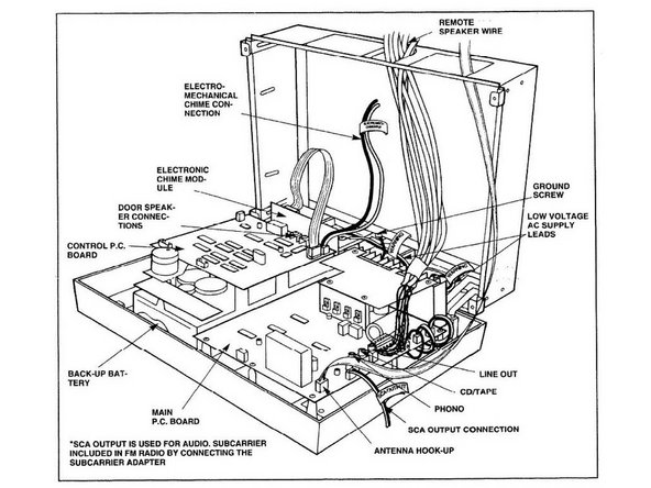
- Note where each wire is connected on the main circuit board. Take photos of the board and the wires.
- Disconnect each of the wires.
- Remove the screws holding the main PC board (about 9 or 10).
- Remove the main PC Board.
- Remove the elevated metal cover from the circuit board. There are 4 Phillips screws.
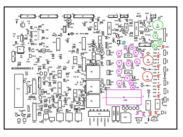
- The main circuit board is pictured. We will be working with the capacitors that I have colored.
- We will remove 31 capacitors. These are on the Master Station Power Supply, the Remote Station Power Supply, the Attenuator and Power Amplifier, and the Microphone Pre-Amplifier.
- The Master power supply capacitors are in red.
- The Remote Station power supply capacitors are in purple.
- The Attenuator and Power Amplifier power supply capacitors are in green.
- The Microphone pre-amplifier capacitor is in blue.
- One at a time, remove and replace each of the 31 capacitors. By doing the complete process for each one you reduce the chance that you will mix up and place a capacitor in the incorrect position.
- Once you have completed replacing the capacitors reassemble the intercom.
- First attach the circuit board back to the intercom.
- Next reconnect each of the wires on the intercom to the circuit board.
- Next attach the metal cover back over the capacitors you replaced.
- Now place the intercom back on the wall
- Reattach all wires that you had disconnected earlier
- Close the intercom and secure at each of the 4 corners.
- Turn the power back on (at the circuit breaker panel).
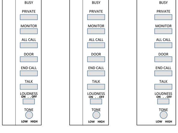
- Many times the labels on the intercom buttons have worn off.
- Attached is a JPG of the label.