Disassembling Acer Aspire 7551G
ID: 48057
Description: Maintenance is an extremely important aspect of...
Steps:
- Remove the battery by sliding the locking latch to the right and pull the battery out.
- Use Phillips #000 Screwdriver to remove the case holding screws, remove the 4 screws that hold the back panel.
- Apply gentle pressure when undoing the screws to preserve the condition of screw heads for future repairs or servicing.
- It is important to manage all the extracted screws in a manner that will allow you to quickly place them where they belong during the reassembly process. You can take pictures of each step to memorize the screw placement, or purchase a magnetic pad and section the screws on it.
- To remove the hard drive, undo the screw that holds it in place and carefully pull the HDD to the right.
- To remove the RAM modules just click the metal levers to the right.
- Remove two black screws from the WiFi card.
- While removing the antenna wires, make sure to memorize or take a picture of their color and position.
- Using the Phillips #000 Screwdriver remove the screw that hold the DVD bay in place.
- Use a spudger to pry the DVD bay away from the case.
- Use Phillips #000 Screwdriver to remove the case holding screws.
- Remember to only apply gentle pressure when undoing the screws to preserve the condition of screw heads for future repairs or servicing.
- Use Phillips #000 Screwdriver to remove the case holding screws.
- Remember to only apply gentle pressure when undoing the screws to preserve the condition of screw heads for future repairs or servicing.
- Use Phillips #000 Screwdriver to remove the case holding screws.
- Remember to only apply gentle pressure when undoing the screws to preserve the condition of screw heads for future repairs or servicing.
- To remove the keyboard, pop the three latches away from the keyboard with a spudger.
- Gently pull the keyboard from the laptop, but be careful not to damage a flex cable that connect it to the motherboard.
- Move the flex cable away from the keyboard.
- Place a Flathead screwdriver under the head of the cable and pry it upwards.
- Use the IC Extractor/Connector Puller to remove the cables.
- These connectors are extremely fragile, only use minimal force and extreme care.
- Use the Phillips #000 Screwdriver to remove the frame screws.
- Apply gentle pressure when undoing the screws to preserve the condition of screw heads for future repairs or servicing.
- Remove all black plastic stickers to reveal the hidden screws.
- Use Phillips #000 Screwdriver to remove the hidden screws.
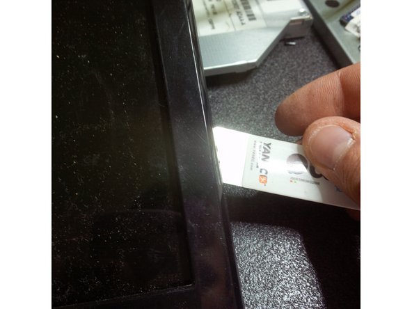
- Carefully slide your prybar under the edge and gently pry around the perimeter.
- Remove the cable from the webcam module
- Remove the screws that hold the screen to the inner frame.
- Apply gentle pressure when undoing the screws to preserve the condition of screw heads for future repairs or servicing.
- Gently unplug the LCD cable.
- Use the iSesamo Opening Tool to pry under the outer edge of the laptop body.
- After hearing the first click, move the tool around the perimeter until all of the clips are undone.
- While some force will be required in this step, make sure not to over-apply pressure since extra force might break the plastic clips.
- After the clips are undone, remove the back cover.
- Carefully remove the ribbon cable connecting the two halves of the motherboard.
- Use Phillips #000 Screwdriver to remove the motherboard screws.
- Apply gentle pressure when undoing the screws to preserve the condition of screw heads for future repairs or servicing.
- Use a plastic prybar to remove the LCD connector. Be careful not to break the cable or its plastic holder.
- Unplug the DC jack cable before removing the motherboard.
- Remove the disconnected DC jack from its holder.
- Carefully lift the motherboard out of the case.
- Use Phillips #000 Screwdriver to remove the screw that is holding the power PCB.
- Apply gentle pressure when undoing the screws to preserve the condition of screw heads for future repairs or servicing.
- If the replacement of the DC jack is necessary, use the IC Extractor/Connector Puller to safely unplug the connection.
- Use the IC Extractor/Connector Puller to safely unplug the fan power connector.
- Use the Phillips #000 Screwdriver to remove the cooling pad screws.
- Apply gentle pressure when undoing the screws to preserve the condition of screw heads for future repairs or servicing.
- Make sure that the screw pressure across the metal plate remain rather constant. Undo the screws by a couple of rotations each, removing them AT the same time.
- Lift the cooling pads and the fan assembly.
- Remove the old thermal compound, degrease the surface with rubbing alcohol.
- Use a can of compressed air to clean the fan assembly.