iPhone 6s Display Replacement
ID: 49759
Description: This guide is retained solely for historical...
Steps:
- Power off your iPhone before beginning disassembly.
- Remove the two 3.4 mm Pentalobe screws surrounding the Lightning connector.
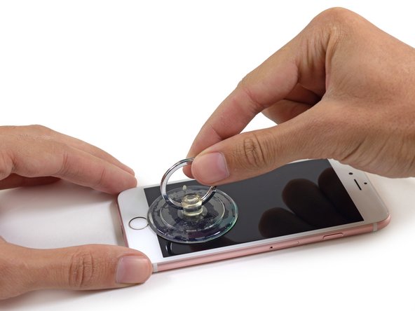
- If you don't have an iSclack, use a single suction cup to lift the front panel:
- Press a suction cup onto the screen, just above the home button.
- Be sure the cup is pressed securely onto the screen to get a tight seal.
- There is a notch on the underside of the display just above the headphone jack that is the safest place to begin prying the phone open.
- Pull up on the suction cup to slightly separate the front panel assembly from the rear case.
- Take your time and apply firm, constant force. The display assembly is a much tighter fit than most devices and is held down with adhesive.
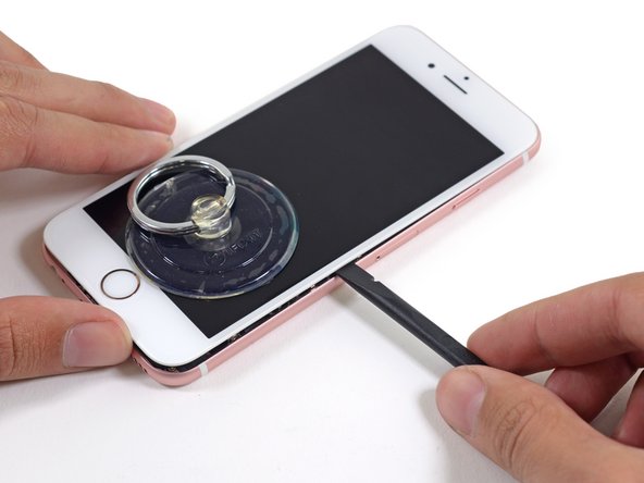
- Once a small gap has been opened, insert the flat end of a spudger above the headphone jack.
- Twist the spudger to open the gap more and break it free from the adhesive.
- Keep pulling up on the suction cup while twisting the spudger.
- Use the edge of a spudger to slice through the adhesive on either side of the phone.
- Use the edge of a spudger to slice through the adhesive on either side of the phone.
- Use the suction cup to open the display, breaking the last of the adhesive.
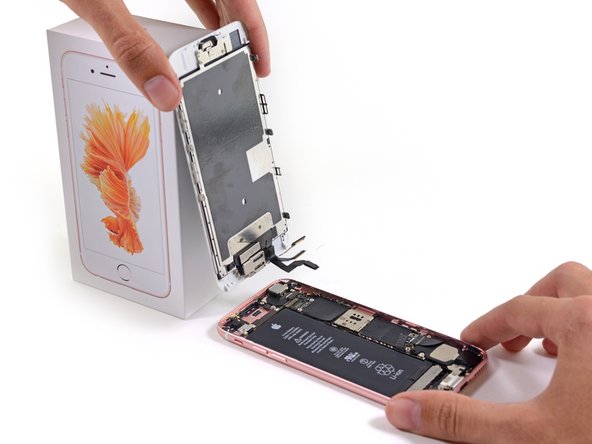
- Don't open the display more than 90 degrees, as it is still connected at the top by three cables that may break if stretched.
- Lean the display against something to keep it propped up while you're working on the phone.
- Remove the following screws from the battery connector bracket:
- One 3.0 mm Phillips #00 screw
- One 2.3 mm Phillips #00 screw
- Remove the metal battery connector bracket from the iPhone.
- Use the flat end of a spudger to disconnect the battery connector from the logic board.
- Push the connector to the side to ensure it doesn't accidentally make contact and power on the phone while you're working on it.
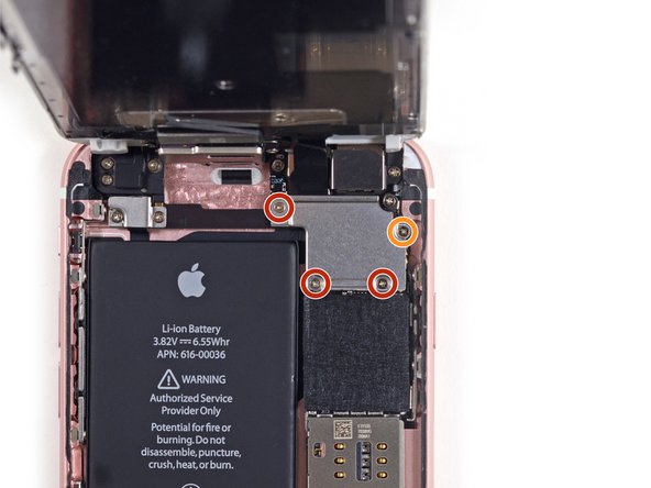
- While holding the front panel open at about a 90º angle, remove the following screws securing the front panel assembly cable bracket:
- Three 1.3 mm Phillips #00 screws
- One 3.0 mm Phillips #00 screw
- Don't lose track of this screw! It's very important that the one 3.0 mm screw goes in the top-right corner of the plate. Anywhere else may cause damage to the logic board.
- Remove the front panel assembly cable bracket from the logic board.
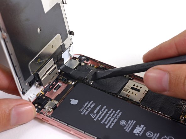
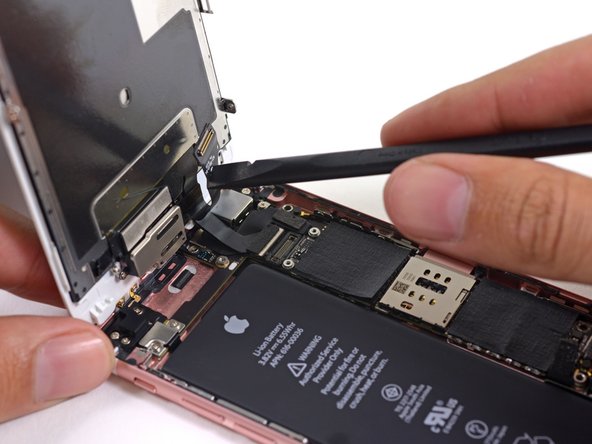
- In the next three steps, take care to pry up only on the cable connectors, and not on their sockets on the logic board.
- Use the flat end of a spudger to disconnect the front-facing camera and sensor cable connector.
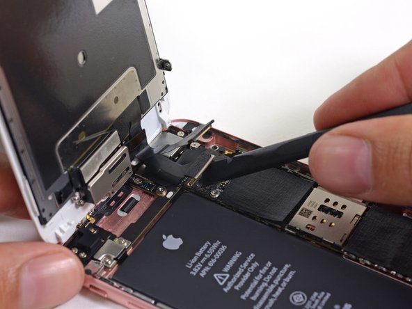
- Use the flat end of a spudger to disconnect the display data cable connector.
- When reassembling your phone, the display data cable may pop off its connector. This can result in white lines or a blank screen when powering your phone back on. If that happens, simply reconnect the cable and power cycle your phone. The best way to power cycle your phone is to disconnect and reconnect the battery connector.
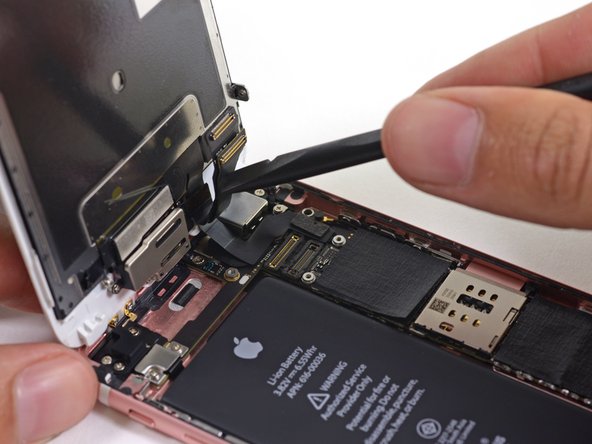
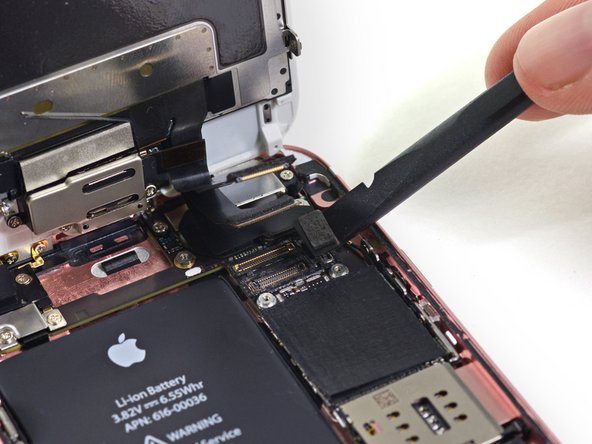
- Finally, use the flat end of a spudger to disconnect the digitizer cable connector.
- Remove the display assembly from the rear case.