Insignia Flex 7 Camera Assembly Replacement
ID: 52114
Description: If your device is not taking picture-perfect...
Steps:
- Insert the edge of the plastic opener into the grove between the screen and back cover around the perimeter of the device.
- Then using a gentle prying motion, create a gap large enough to use your fingers to separate the two halves.
- Place the tip of the spudger on each side of the battery's electrical connector.
- Then using a gentle match-striking motion, loosen both sides of the battery's electrical connector.
- Insert the flat end of the spudger under one side of the battery.
- Then using a gentle prying and sliding motion, separate the battery from the case. There are two lengthwise strips of glue holding it down.
- Repeat the process for the other side of the battery.
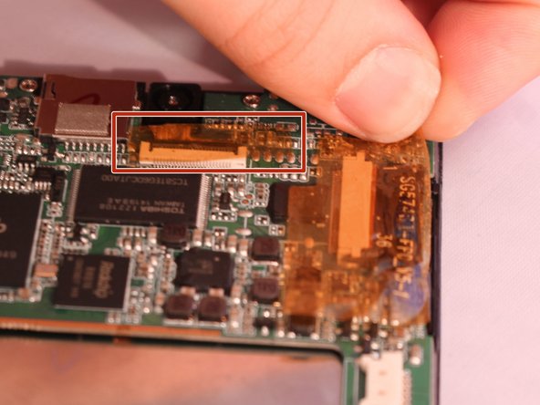
- Locate the three ribbon cables connecting components to the motherboard. The connections are covered with orange shielding tape. Peel the tape off the connectors and reserve for reassembly.
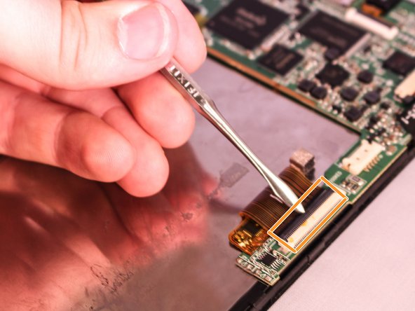
- Each Zero Insertion Force or ZIF connector has a latch which holds the ribbon cable in place. The camera cable (a) and the LCD display cable (b) have a latch that lifts as shown in the illustration. Use a spudger to gently lift the latch to release the cable.
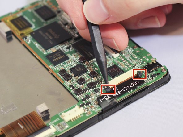
- The touchscreen cable (c) has a sliding latch on each side of the connector. Use a spudger to carefully slide the latch on each side as shown to release the cable.
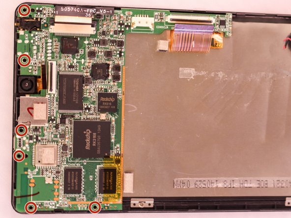
- Using a Phillips #000 screwdriver, unscrew the six 4.8mm screws holding the motherboard to the case.
- Using the spudger lift the motherboard from the case.
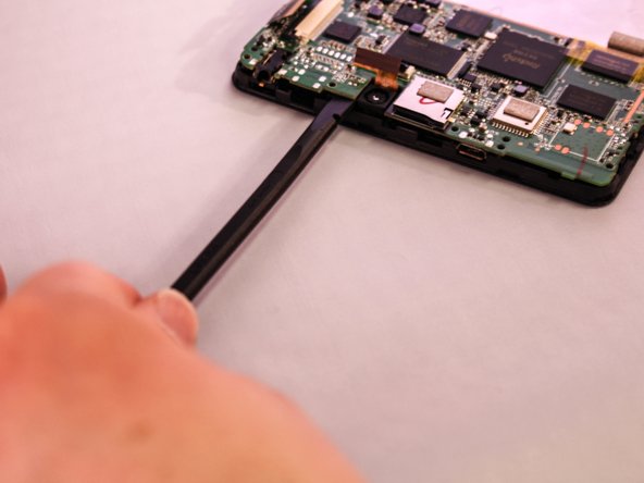
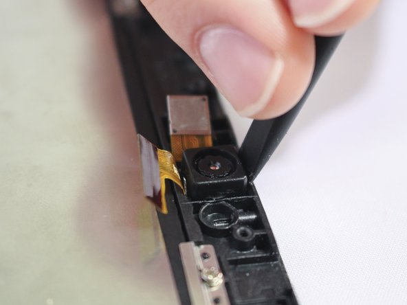
- Insert the flat end of the spudger into the groove between the external camera and the tablet's plastic case. Then, applying a gentle prying motion on both sides of the camera, loosen the glue holding down the external camera to separate it from the plastic case.