Insignia Flex 7 Motherboard Replacement
ID: 52115
Description: In this guide we will show how to properly remo...
Steps:
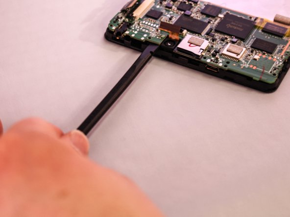
- Insert the edge of the plastic opener into the grove between the screen and back cover around the perimeter of the device.
- Then using a gentle prying motion, create a gap large enough to use your fingers to separate the two halves.
- Place the tip of the spudger on each side of the battery's electrical connector.
- Then using a gentle match-striking motion, loosen both sides of the battery's electrical connector.
- Insert the flat end of the spudger under one side of the battery.
- Then using a gentle prying and sliding motion, separate the battery from the case. There are two lengthwise strips of glue holding it down.
- Repeat the process for the other side of the battery.
- Using a Phillips #000 screwdriver, remove the two 3.0mm long screws shown in the illustration.
- Using the spudger, gently pry the speaker from it’s plastic socket.
- Apply heat to the solder junction of the red wire with a solder iron.
- Once the solder melts, the wire can be disconnected from the circuit board. To do so, use tweezers to apply a gentle tension to the wire when the solder appears fluid.
- During reassembly, the reversal of this step is slightly different. First, apply heat with the iron, then place the wire on the solder pin. Once the solder flows over the wire, pull the iron away and wait for the solder to solidify.
- Repeat the previous step to separate the speaker's black wire from the motherboard.
- During reassembly, the reversal of this step is slightly different. First, apply heat with the iron, then place the wire on the solder pin. Once the solder flows over the wire, pull the iron away and wait for the solder to solidify.
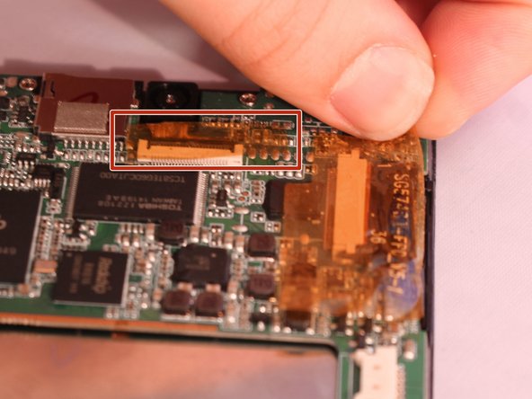
- Locate the three ribbon cables connecting components to the motherboard. The connections are covered with orange shielding tape. Peel the tape off the connectors and reserve for reassembly.
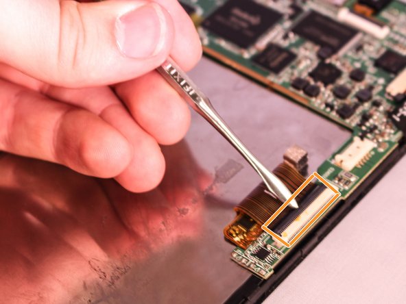
- Each Zero Insertion Force or ZIF connector has a latch which holds the ribbon cable in place. The camera cable (a) and the LCD display cable (b) have a latch that lifts as shown in the illustration. Use a spudger to gently lift the latch to release the cable.
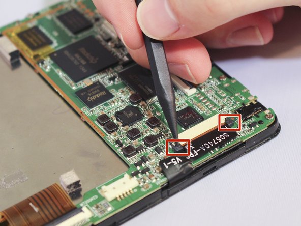
- The touchscreen cable (c) has a sliding latch on each side of the connector. Use a spudger to carefully slide the latch on each side as shown to release the cable.
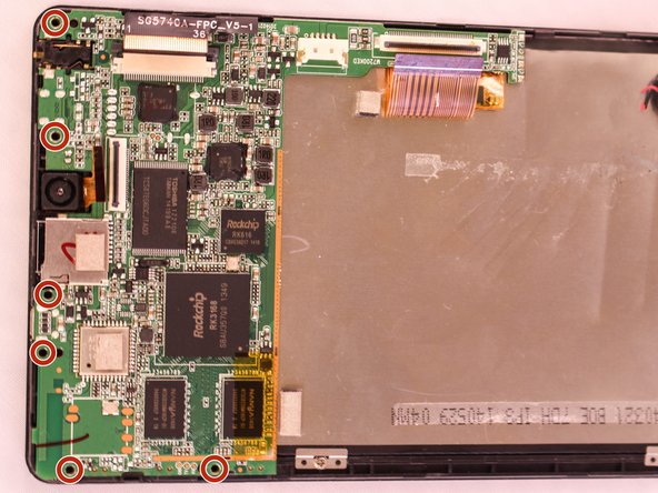
- Using a Phillips #000 screwdriver, unscrew the six 4.8mm screws holding the motherboard to the case.
- Using the spudger lift the motherboard from the case.