Nikon D3000 On/Off Switch and Shutter Button Replacement
ID: 52160
Description:
Steps:
- Remove six 3 mm x 2.5 mm Phillips head screws from the bottom of the camera.
- Remove three 3 mm x 5.5 mm Phillips head screws from the bottom of the camera near the battery cover.
- Lift the battery cover and remove two 3 mm x 5.5 mm Phillips head screws as shown.
- Remove the bottom cover.
- Remove two 3 mm x 5.5 mm Phillips head screws from either side of the viewfinder.
- Remove four 3 mm x 5.5 mm Phillips head screws above and below the USB port cover and on either side of the SD card slot cover.
- Remove two 3 mm x 4 mm Phillips head screws inside the SD card slot cover.
- Lift the LCD panel off up to expose a ribbon connector. Then lift the ribbon connector tab as shown and slide the ribbon out.
- Use this technique for all ribbon connectors in this guide.
- Lift the LCD panel away and off the camera
- Remove six 3 mm x 5.5 mm Phillips head screws from around the lens ring and remove the lens ring.
- Remove two 2.5 mm x 4 mm Phillips head screws from above the lens ring to allow the front of the camera to be removed.
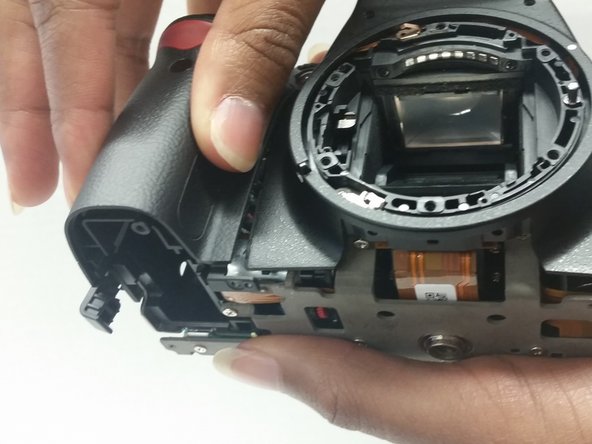
- Lift and remove the grip and the front panel of the camera.
- Remove two 3 mm x 4 mm Phillips head screws from where the camera grip was just removed.
- Remove one 2 mm x 3 mm Phillips head screw from the same location as above.
- Remove one 3 mm x 5.5 mm Phillips head screw from the top right side of the camera shown.
- Remove one 3 mm x 3 mm Phillips head screw from the top left side of the camera shown.
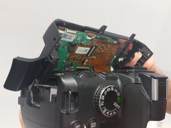
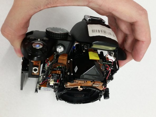
- Gently lift the top of the camera up to separate it from the main body of the camera. At this point, it will still be connected via wires.
- Soldering irons are hot. Take all necessary precautions before soldering to prevent damage to the camera or yourself.
- De-solder the wire shown on the grip side of the camera to allow sufficient access to the top of the camera.
- Remove the ribbon connector.
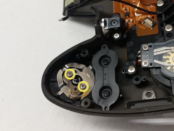
- Remove the 3 mm x 4 mm Phillips head screw and lift off the plastic bracket to expose the on/off switch underneath.
- A quick inspection should take place before replacing the button and the metal contacts.
- Remove the two 2 mm x 4 mm Phillips head screws and the shutter button and on/off switch will fall down away from the top of the panel.