MacBook Pro 15" Retina Display Mid 2015 Logic Board Assembly Replacement
ID: 56022
Description: Prerequisite to remove the logic board assembly...
Steps:
- Remove the two 2.2 mm Torx T5 screws securing the touchpad cable connector cover to the logic board.
- Remove the cover.
- Use the flat end of a spudger to disconnect the touchpad cable connector from its socket in the logic board.
- Slightly twisting the flat end of a spudger is an easy way to pry up the cable connector from these types of sockets.
- Be careful to only pry up against the connector, and not the logic board socket.
- Remove a small rubber cap off the screw at the end of the heat sink.
- Remove the following six screws securing the logic board assembly to the upper case.
- One 3.8 mm T5 Torx screw
- Two 5.7 mm T5 Torx screws
- One 5.6 mm T5 Torx screw (this one is silver and has a taller head than the others)
- One 2.6 mm T5 Torx screw
- One 3.2 mm T5 Torx screw
- On reassembly, start all six screws but do not tighten any of them. Move the logic board around until all of the screws are centered in their holes and the ports are lined up with their openings in the side of the upper case. Then tighten all of the screws.
- The following steps will detail disconnecting these six connectors. Be sure to read each step, as these connectors come in different styles that disconnect differently.
- Microphone cable
- Left speaker cable
- Keyboard data cable
- Right speaker cable
- Keyboard backlight cable
- Display data cable
- On reassembly, check to make sure all of these connectors are connected and fully seated in their sockets.
- Use the tip of a spudger to flip up the retaining flap on the microphone ribbon cable ZIF socket.
- Pull the microphone ribbon cable out of its socket, parallel to the logic board.
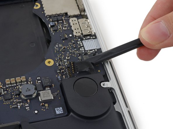
- Use the flat end of a spudger to pry the left speaker connector up and out of its socket on the logic board.
- Be sure to pry on the cable connector and not on the socket on the logic board. Prying on the socket may cause it to separate from the logic board.
- Gently fold the cable up and out of the way of the logic board.
- Peel back the tape covering the top of the keyboard data cable connector.
- Use the tip of a spudger to flip up the retaining flap on the keyboard data cable ZIF socket.
- Be sure you are prying up on the hinged retaining flap, not the socket itself.
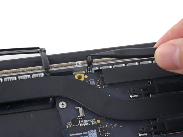
- Pull the keyboard data cable out of its ZIF socket. Be sure to pull parallel to the logic board, and not straight up.
- Use the tip of a spudger to pry the right speaker connector up and out of its socket on the logic board.
- Be sure to pry on the cable connector and not on the socket on the logic board. Prying on the socket may cause it to separate from the logic board.
- Gently fold the cable up and out of the way of the logic board.
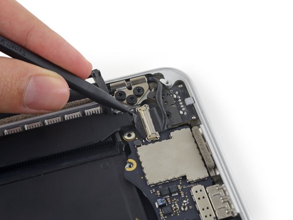
- Use the point of a spudger to pry the keyboard backlight connector up from its socket on the logic board.
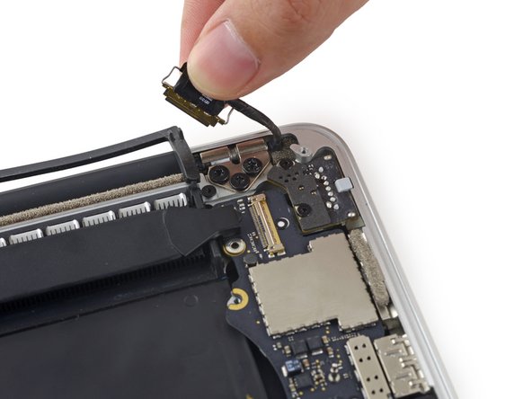
- Use the tip of a spudger to flip up the display data cable lock and rotate it toward the MagSafe 2 power port side of the computer.
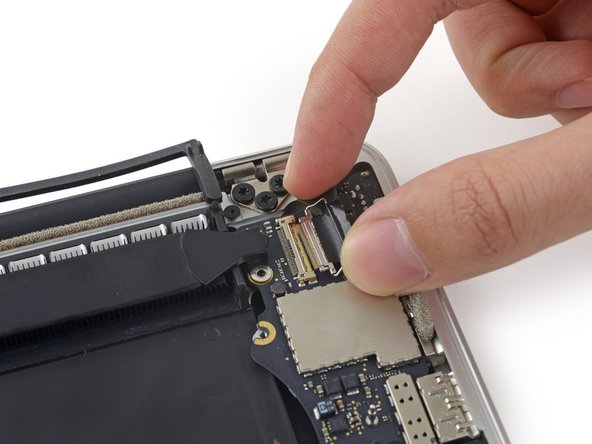
- Pull the display data cable straight out of its socket on the logic board.
- Do not lift up on the display data cable, as its socket is very fragile. Pull the cable parallel to the face of the logic board.
- Do not touch the contacts on the data connector or its socket with your fingers or any tools, as you may deposit oils or damage the pins.
- Gently bend the display data cable toward the display hinge, to expose the screws on the MagSafe 2 board.
- Remove the two 4.0 mm T5 Torx screws from the MagSafe 2 board.
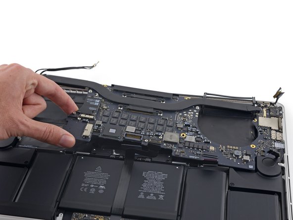
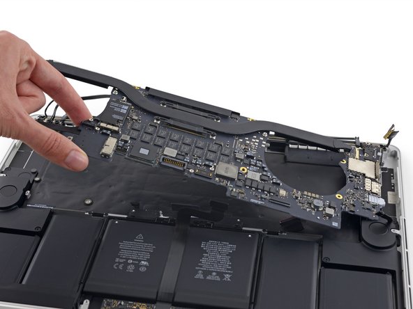
- Lift and pull the entire logic board assembly away from the wall of the upper case.
- When reassembling, be sure to line up the ports with their cutouts in the upper case.