Samsung SGH-A737 Camera Replacement
ID: 56061
Description: If you're experiencing issues with your Samsung...
Steps:
- Gather all the materials required prior to the teardown.
- A Phillips PH000 screw head and screwdriver are the only required tools for this guide.
- Make sure to use the correct screwdriver head in order to avoid damaging screw heads.
- Avoid over tightening the screws to avoid damaging them.
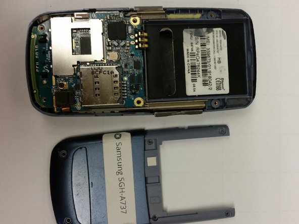
- Remove the battery from the back of the device.
- To do this, slide the battery cover off the rear side of the phone.
- Once the rear cover is removed, the battery should easily pop out of the phone.
- Using the screwdriver, unscrew the six visible screw drivers on the back of the phone.
- Be sure to use the proper size of screwdriver. If you don't you may risk damaging the outer container of the device.
- Next, remove the side buttons by gently prying them off.
- When the phone is reassembled, these buttons will be placed back in their appropriate holder.
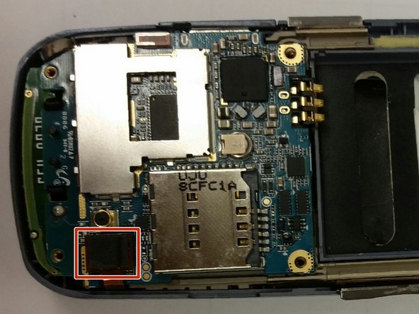
- With care, lift up the connector located at the bottom left of the phone, as demonstrated in the accompanying image.
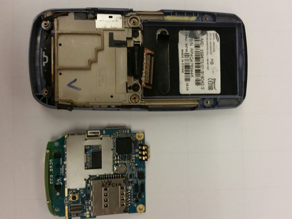
- Flip the circuit board up to unveil an orange connector near bottom of it.
- Gently unplug the connector by prying on the corner with a finger.
- Lift up the tan circuit board holder to separate it from the device.
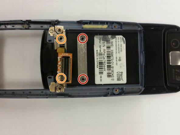
- Peel off the black strip below the product sticker, unveiling two screws and unscrew them.
- There are two more screws slightly below that need to be unscrewed as well.
- Be sure to use the proper size screwdriver. Using the wrong size can cause damage to the case!
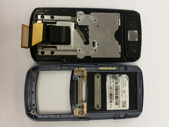
- Make sure the phone is closed. If not slide it closed now.
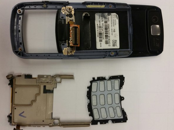
- Next, carefully detach the blue plastic panel from the phone. It should already be slightly loose.
- When sliding the connector through the rectangular gap, be sure to do so gently in order to avoid any damage.
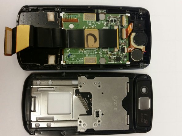
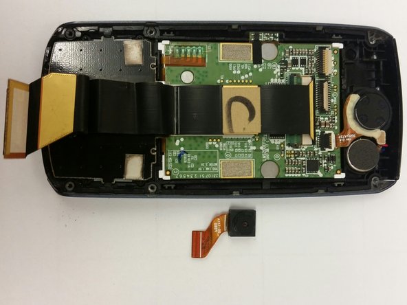
- Begin by removing the six visible screws located on the outer edge of the device.
- Once the screws are removed, gently separate the panel to unveil the circuits and camera.
- Be sure to perform these steps using as little force as possible. The circuit boards can be delicate!
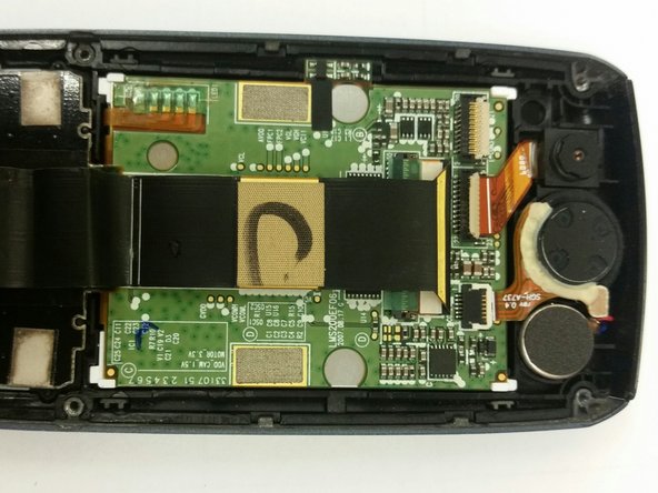
- To disconnect the camera, gently lift the tan flap away from the camera where the orange connector is attached. This should loosen the wire.
- Next, pry up on the camera to dislodge it. This may require some force.