Fairphone 1 RF Cable Replacement
ID: 56270
Description: Use this guide to replace just the RF Cable on...
Steps:
- There is a small indentation in the side of the phone near the bottom of the back cover.
- With the indentation as leverage, use your fingernail to pry the bottom portion of the back cover from the phone.
- Slide the back cover down and remove it from the phone.
- There is a small indentation in the back of the phone just below the battery.
- Use a fingernail in this indentation to push the battery toward the top of the phone
- Pull the battery out away from the phone.
- Remove the battery from your Fairphone.
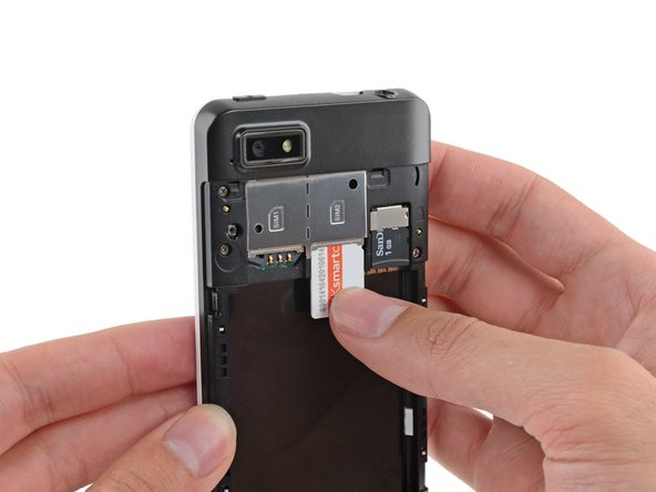
- Use your finger to slide the SIM card straight down out of its tray.
- Remove the SIM card from your Fairphone.
- Repeat this procedure if you have a second SIM card.
- Be sure to remove all SIM cards before servicing your phone.
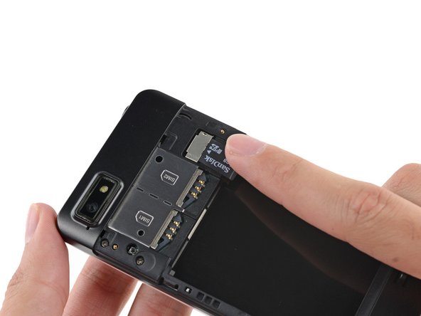
- If you have a microSD card, use your finger to slide it straight out of its slot.
- Remove the microSD card from your phone.
- Remove the five 3.9 mm Phillips #000 screws securing the midframe to the display assembly.
- The midframe is secured to the display assembly by several small plastic clips.
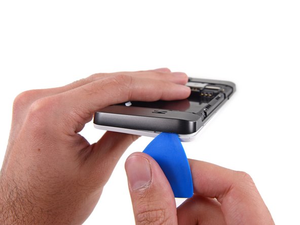
- Use an opening pick to carefully pry the midframe away from the display assembly.
- Start just below the volume rocker and work your way down toward the bottom of the phone, freeing the plastic clips along the side.
- Carefully round the corner, separating the midframe from the display assembly.
- After rounding the next corner, the midframe should be free along the bottom and the sides.
- Run the opening pick and pry along the top seam.
- To avoid bending or damaging the opening picks, do not pry near to the power switch, USB port, or headphone jack.
- Separate any remaining clips and remove the midframe from the phone.
- Use tweezers to remove the volume rocker and power buttons from the display assembly.
- During reassembly make sure the orientation of the buttons is correct. The rubber backings must fit into the channels in the assembly.
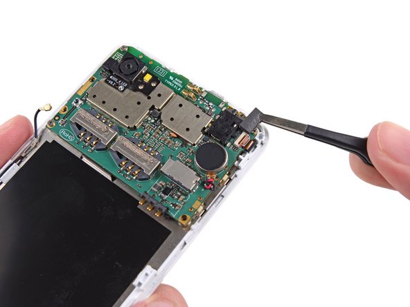
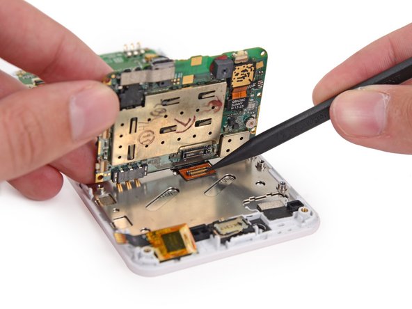
- Use the flat end of a spudger to disconnect the antenna cable connector.
- Make sure to only disconnect the connector from its socket, and not the entire socket from the board.
- Use tweezers to remove the adhesive foam tape from the top of the digitizer cable ZIF socket.
- Use the tip of a spudger to flip open the tab on the digitizer ZIF connector.
- Use tweezers to pull the digitizer cable away from its socket on the motherboard.
- Remove the three 2.5 mm Phillips #000 screws securing the motherboard to the display assembly.
- Do not try to remove the motherboard just yet, as it is still connected to the display assembly by the display data cable.
- Gently lift the top end of the motherboard up to expose the display data cable.
- The rear-facing camera may be adhered to the display assembly. Try to pry it and the motherboard up together.
- Use the tip of a spudger to disconnect the display data cable from the back of the motherboard.
- Remove the motherboard from the display assembly.
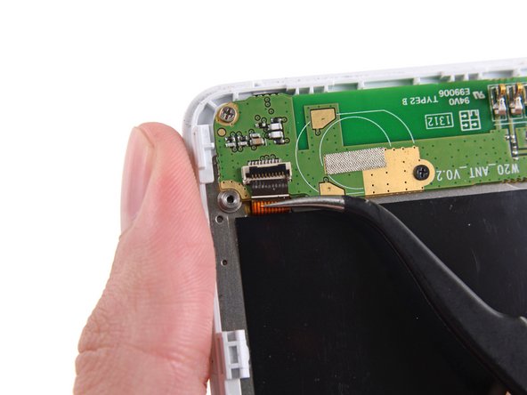
- Use the flat end of a spudger to disconnect the antenna cable connector.
- Be careful to pry on the connector, not the socket.
- Use the tip of a spudger to flip open the tab on the daughterboard data cable ZIF connector.
- Use tweezers to pull the daughterboard data cable away from its socket.
- Remove the following screws securing the Wi-Fi daughterboard to the display assembly:
- Two 2.5 mm Phillips #000 screws
- One 1.6 mm Phillips #000 screw
- The Wi-Fi antenna daughterboard is held to the front assembly by mild adhesive.
- Use tweezers to gently pry the board up and remove it from the phone.
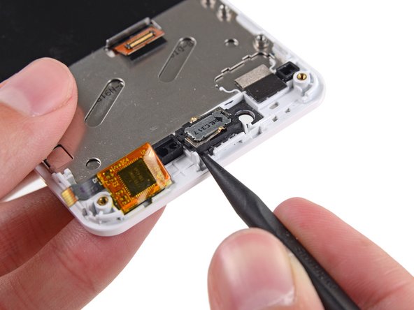
- The earpiece speaker is held to the back of the display assembly with some mild adhesive.
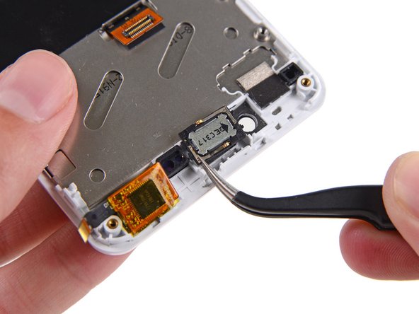
- Use the tip of a spudger to gently pry the speaker up from the display assembly.
- Remove the speaker.
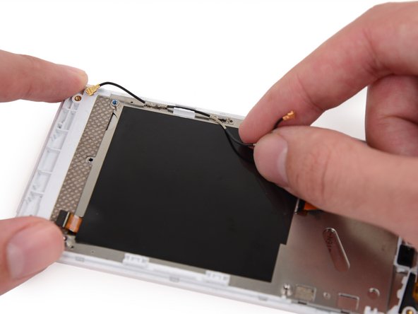
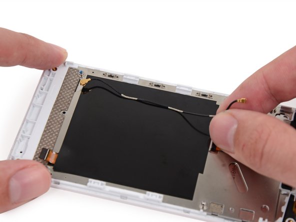
- Remove the antenna interconnect cable from the display assembly.
- The three sections of the cable with exposed metal fit into the grounding clips on the side of the display assembly.