Fujifilm X-M1 Disassembly
ID: 56288
Description: This guide gives you a look at the major...
Steps:
- If you haven't done so already, remove the lens from the camera.
- Remove the six 2.5 mm Phillips screws from the bottom of the camera.
- Use tweezers or a finger nail to peel back the rubber cover on the left handgrip.
- Remove the 3.4 mm Phillips screw.
- Remove the 3.7 mm screw.
- Use tweezers or a fingernail to peel back the rubber cover on the right handgrip.
- Remove the 3.2 mm Phillips screw.
- Remove the 3.8 mm Phillips screw.
- Remove the 2.8 mm Phillips screw.
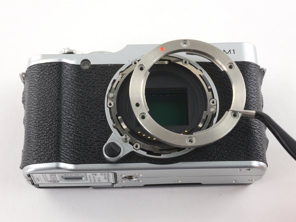
- Remove the six 6.5 mm Phillips screws from the lens mount.
- Use tweezers to remove the top metal ring and the thin metal ring below it .
- Remove the four 4.3 mm screws securing the sensor to the front case.
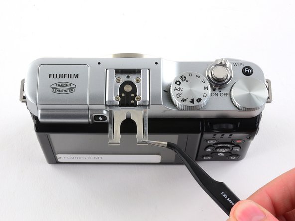
- Use tweezers to slide the metal shield straight out of the external flash mount.
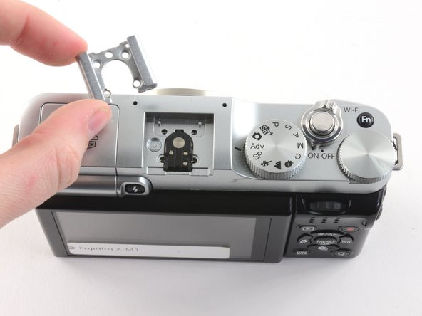
- Remove the four 4.6 mm Phillips screws from the external flash mount.
- Use tweezers or two fingers to remove the mount clip.
- Extend the LCD.
- Remove the two black 4.3 mm Phillips screws from the back case.
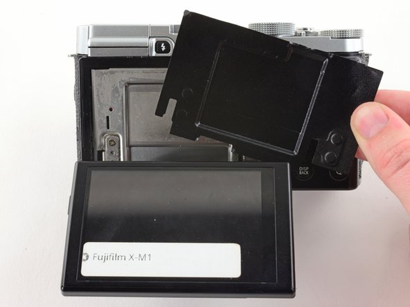
- Use two fingers to peel back and remove the black plastic cover from behind the LCD.
- Slowly pull the back frame away from the camera.
- Do not attempt to remove the frame, as it is attached to the camera by a ribbon cable.
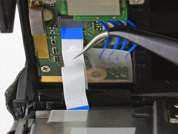
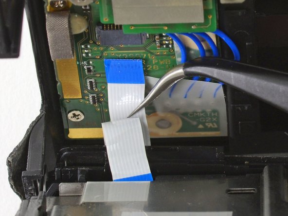
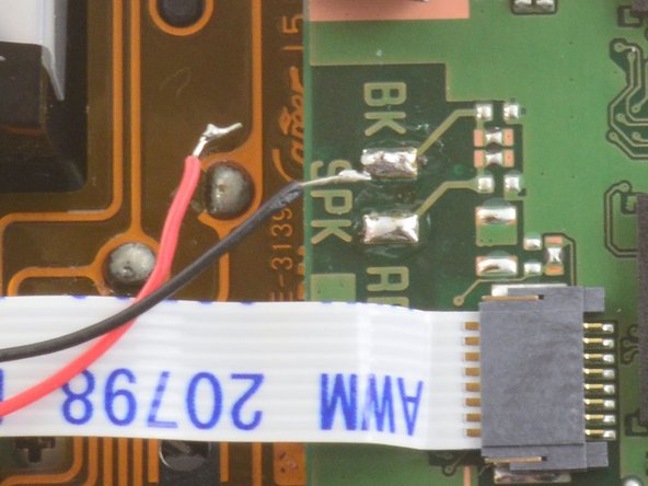
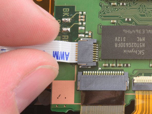
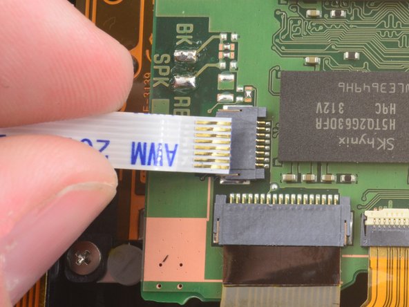
- Use tweezers to pull the white and blue ribbon cable out of the connector.
- Slide the frame around the LCD to remove it from the camera.
- Remove the two 2.6 mm Phillips screws from the right side of the metal frame.
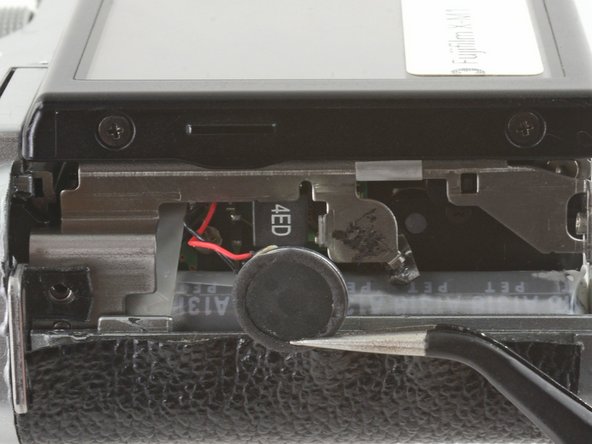
- Use tweezers to unhook the speaker near the left handgrip.
- Slowly lift the metal frame away from the motherboard.
- Do not attempt to remove the frame, as it is attached to the motherboard by a large ribbon cable.
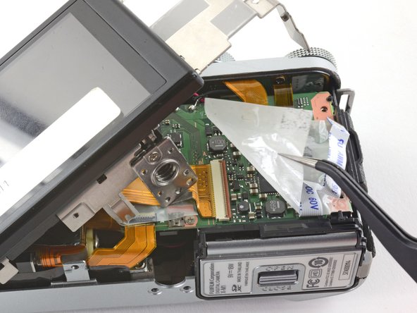
- Use tweezers to remove the plastic covering the motherboard.
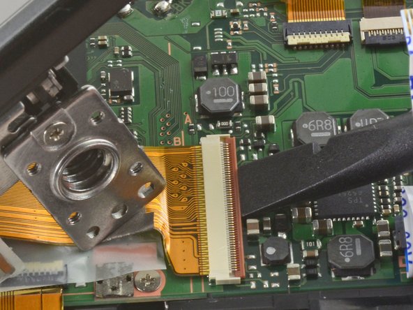
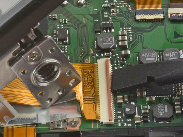
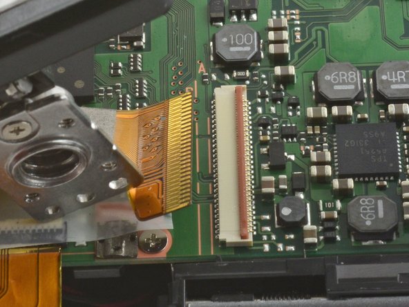
- To remove the ribbon cable, flip back the orange lock on the large ZIF connector with the flat end of a spudger.
- If the ribbon cable does not pop out on its own, use tweezers to pull it out of the connector.
- Use tweezers to remove the three pieces of tape covering the components of the motherboard.
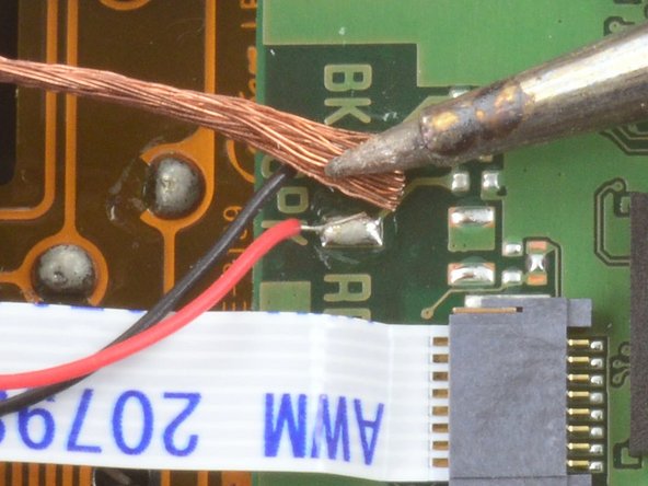
- Desolder the three pairs of red and black wires attached to the mother board.
- Learn more about desoldering wires here.
- Use tweezers to remove the grey cushion located below the flash button.
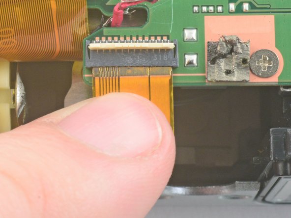
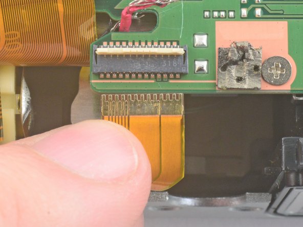
- Use two fingers to remove the two ribbon cables in the bottom left corner of the motherboard.
- Use the flat end of a spudger to unlock the four indicated ZIF connectors.
- Use two fingers to pull the ribbon cables out of the connectors.
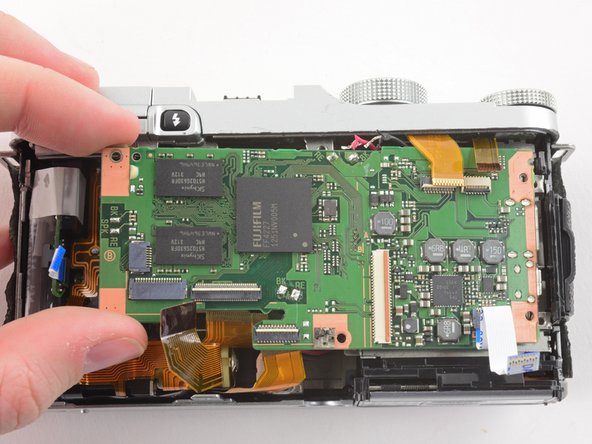
- Remove the 3.3 mm Phillips screw from the upper left corner of the motherboard.
- Remove the 2.4 mm Phillips screw in the bottom right corner of the motherboard.
- Use two fingers to remove the motherboard from the front case.
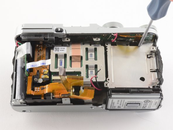
- Use tweezers to remove the black plastic tape at the top of the battery compartment.
- Insert a Phillips #00 screwdriver through the hole beneath the black tape to remove a 4.8 mm screw.
- Insert a Phillips #00 screwdriver through the white tamper evident sticker to remove a second 4.8 mm screw.
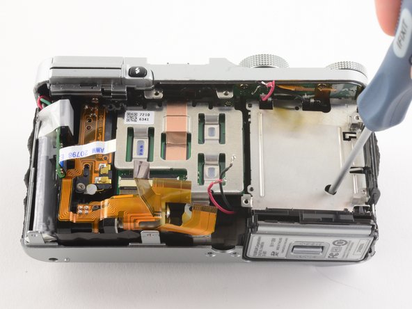
- Remove the 3.7 mm Phillips screw from the bottom of the sensor mount.
- Remove the 4.2 mm Phillips screw from the bottom of the sensor mount.
- Remove the 6.2 mm Phillips screw hiding between the sensor mount and the battery compartment.
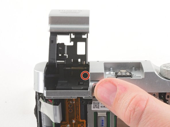
- Press the flash button to release the flash assembly.
- Remove the 3.4 mm Phillips screw in the back of the flash compartment.
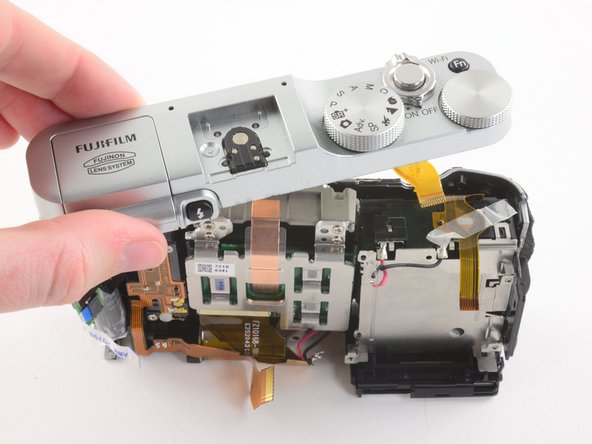
- Remove the top plate.
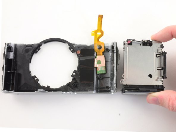
- Remove the sensor assembly.
- Remove the battery compartment.
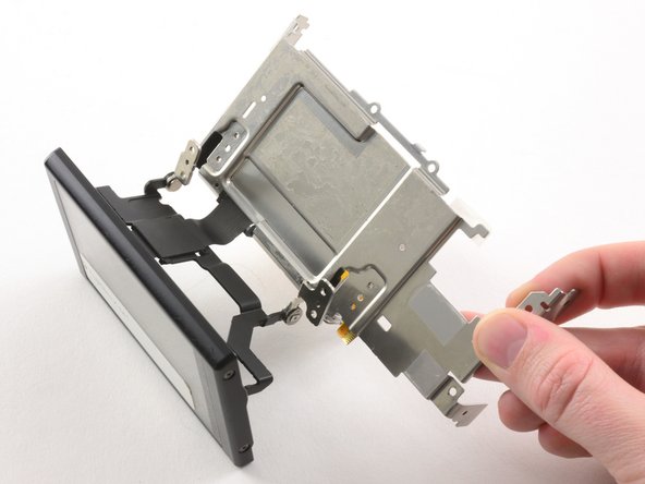
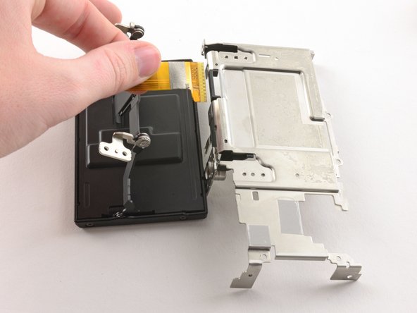
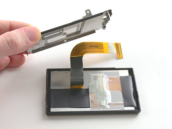
- Remove the four 2.6 mm Phillips screws from the LCD hinges.
- Tilt the LCD away from the metal frame.
- Do not attempt to remove the LCD, as it is attached to the metal frame by a ribbon cable.
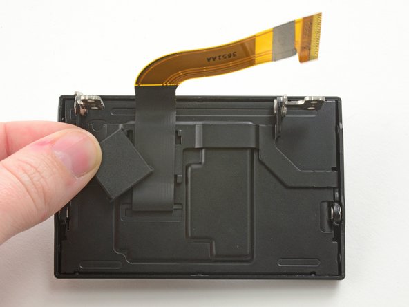
- Use two fingers to pull the ribbon through the hole in the metal frame.
- Remove the LCD from the metal frame.
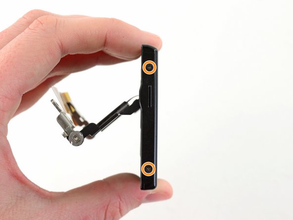
- Use the pointed end of a spudger to remove the ribbon cover on the back of the LCD.
- Remove the two 2.6 mm Phillips screws from the right hand side of the LCD screen.
- Remove the two 2.6 mm Phillips screws from the left hand side of the LCD screen.
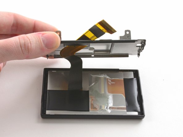
- Use a plastic opening tool to pry the LCD case open.
- Once the case is open, pull the ribbon through the hole on the back case.
- Remove the LCD from the screen cover.
- You have successfully disassembled the Fujifilm X-M1!