How to make SolarSPELL
ID: 56443
Description: Here are the steps for creating a SolarSPELL of...
Steps:
- Make sure to drill on a drilling surface.
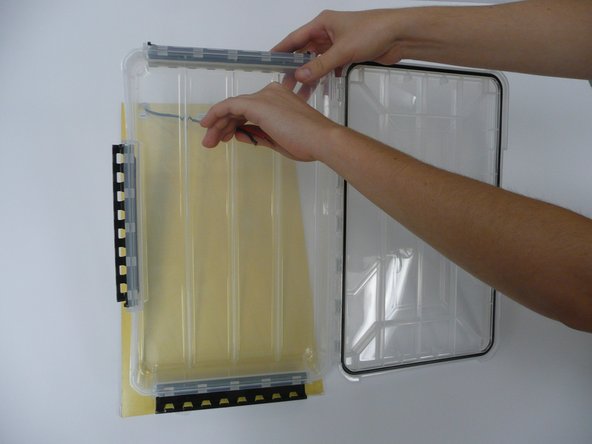
- Open the clear plastic box and place face down on a drill-able surface.
- From the back of the box, drill through the indented ridge about 6 cm down from the short edge of the box with about a quarter inch drill bit.
- Ensure the drill bit goes through to the other side so that the hole is the same size from the front and from the back.
- This step might vary depending on how the voltage regulator comes
- Make sure to not cut the mini USB off of the voltage regulator
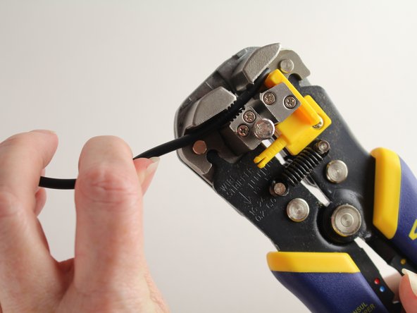
- Cut the open wire side (the side that the red arrow points to)
- Use wire cutters to cut the wire so that there is only about 3 inches left from the voltage controller (where the purple arrow is pointing)
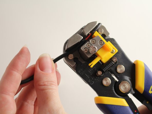
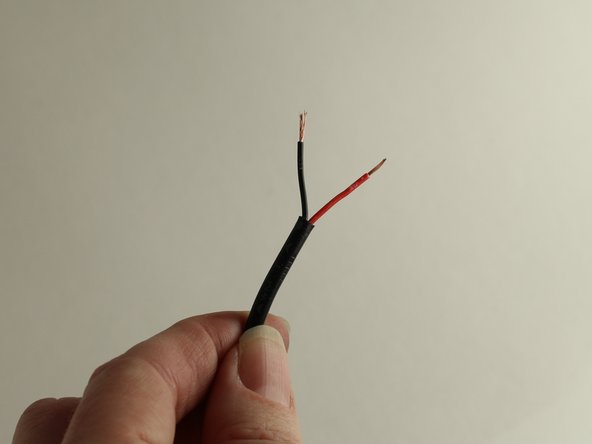
- The voltage regulator should look like the one in the second picture and the end of the wire will look like the third picture
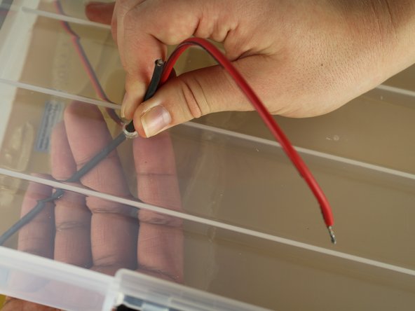
- There are two insulated copper wires inside the outer wire jacket, so two different types of wire stripping must occur
- First, the outer jacket of the wire must be stripped. Keep in mind that there are two smaller wires on the inside
- Be gentle with this first wire strip and only pull off the outer wire jacket.
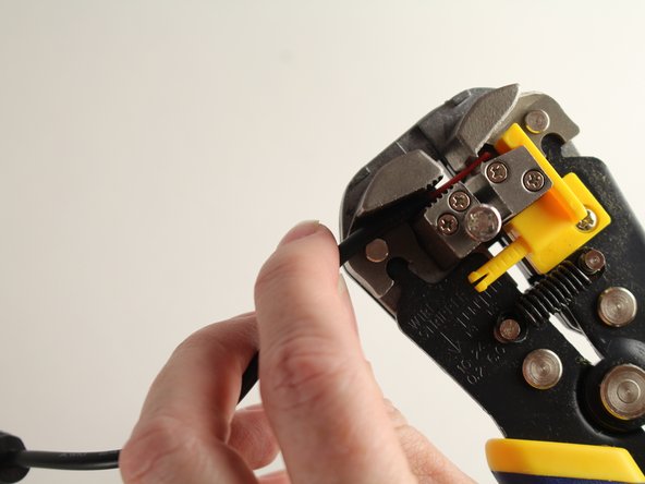
- Strip about an inch of the outer wire jacket off of the wire.
- The outer jacket will now be cut loose.
- Pull this loose piece of rubber off of the end of the wire to access the smaller black and red insulated wires below.
- Use the wire strippers to strip the red and black insulation off of the copper core.
- Strip about half an inch from both black and red wires.
- This can be done at the same time, in the wire stripper together.
- If the solar panel comes with some form of attachment, the attachment to the wires will need to be cut off leaving 10-12 inches of wire still attached.
- This step will change depending on the type of solar panel used
- String the wires through from the back of the panel through the hole on the outside of the box
- Make sure the light-catching side of the solar panel is exposed when the box is closed and placed face down
- Both red and black wires will need to be stripped of the insulation to expose the copper core.
- Refer to Step 3 for instructions on how to wire strip.
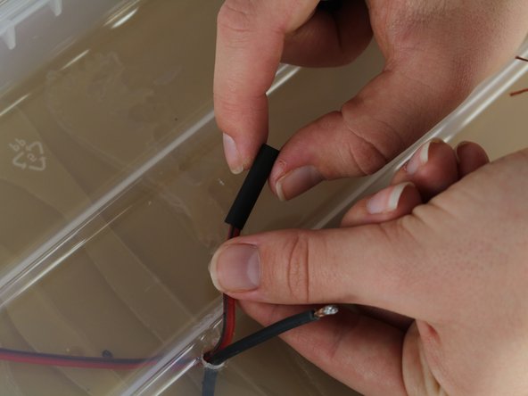
- String heat shrink tubing onto both the red and the black solar panel wires separately using heat shrink that is between 3/16" and 3/32".
- String heat shrink tubing on the wire of the voltage regulator using heat shrink that is 1/4" to 1/8".
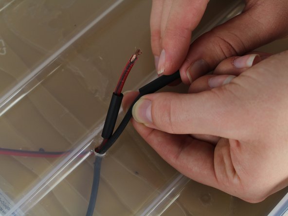
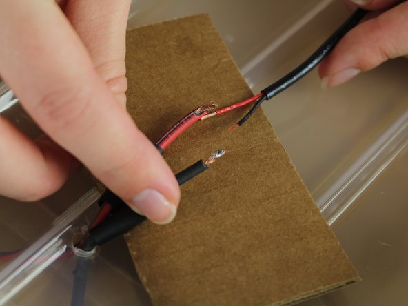
- Bring the voltage regulator wires to the solar panel wires and prepare to solder.
- Make sure you solder red to red and black to black.
- Make sure to solder on top of a scrap piece of wood or other material. Do not solder over the open box in case solder drips down into the box.
- For instructions on how to solder please visit: Soldering Skills
- Once the wires are soldered together, pull the heat shrink from the solar panel wires down to cover the soldered part and any exposed copper.
- Leave the heat shrink tube from the voltage regulator where it is for now, the heat shrink must be done in two separate steps.
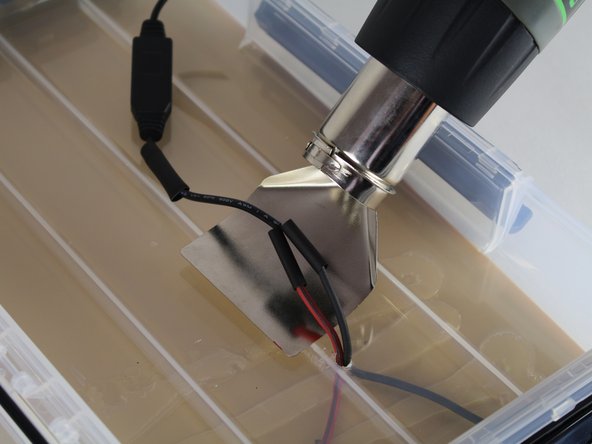
- Use the heat gun to shrink the wrap strung on the two solar panel wires that are now covering the soldered connection.
- A reflector nozzle was used on the heat gun, as shown.
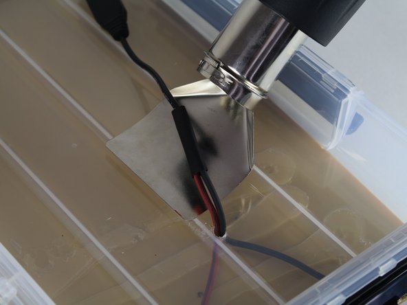
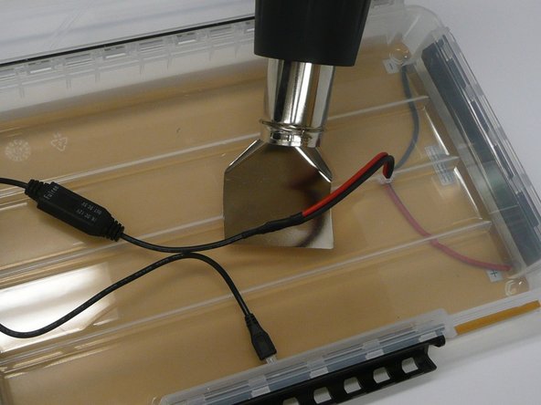
- Now, pull the heat shrink tubing that was strung on the voltage regulator down over the wires that were just heat shrunk.
- Heat shrink this wrap until the rubber wraps neatly around the wires, ensuring the edges are sealed.
- Pull this wire connection so that the solar panel lies tight against the back of the box.
- Flip the box over and pull the solar panel up off the back of the box to access the back of the box, making sure the wires stay tightly pulled from the inside.
- Assemble the glue gun based on the instructions that are included with the gun.
- The box is made of polypropolene which is a very challenging material to glue. There are other glues that could be used, but this glue works very well.
- Glue the hole where the solar panel wires are strung to the inside of the box closed.
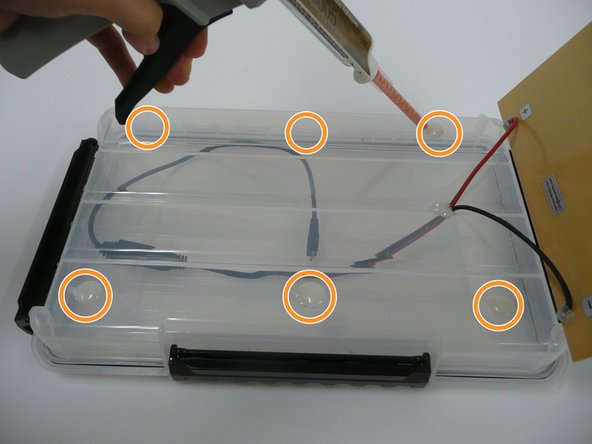
- Inject the glue in quarter-sized circles on the outside edges of the box. 6 spots of glue should suffice.
- Pull the panel down over the glue making sure it is centered on the box.
- Let the glue dry for 24 hours before continuing.
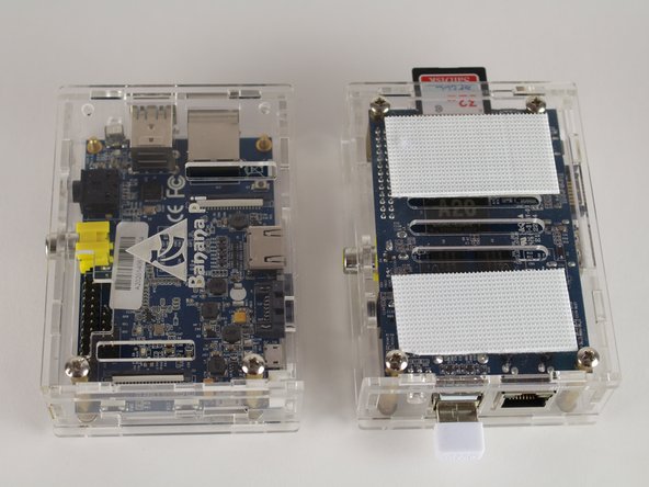
- If the Banana Pi does not come with the protective case already, it will need to be built according to the case instructions.
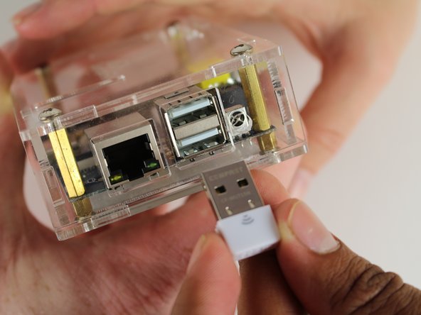
- Insert the WiFi Dongle into either one of the USB ports. It does not matter which port.
- Download the SPELL site to a 64 GB memory card.
- This step is not yet available.
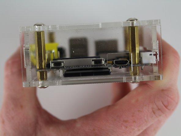
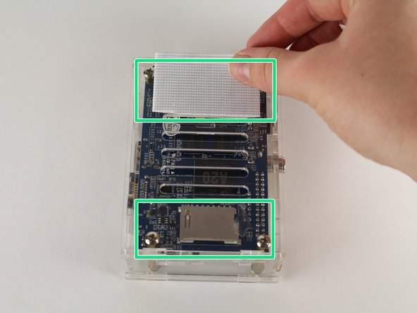
- Insert the chip in the slot of the Banana Pi as shown.
- Please refer to this website for the description of hook and loop.
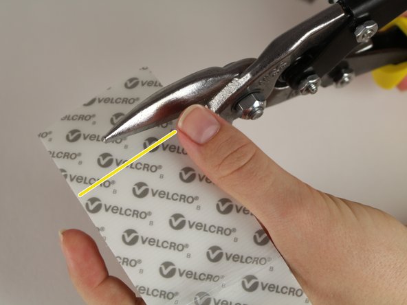
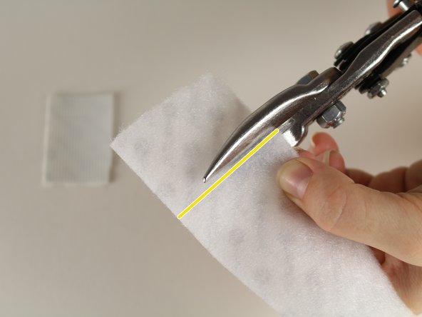
- Measure pieces of the hook side of Velcro to be about 1 and 1/2 inches.
- Use a pair of heavy duty scissors (sheet metal shears were used) to cut the heavy duty Velcro hook side.
- Repeat this step three times until you have 4 strips of hook side velcro
- Peel the backing off of the hook side of the Velcro
- Apply the velcro to the two marked sites on the bottom of the Banana Pi
- The banana pi computer will now appear as shown (before and after).
- Again, peel the backing off of the hook side of the Velcro for the remaining 2 cut pieces.
- Apply the other two strips of the hook side Velcro to the top and bottom of the battery.
- Measure the Velcro loop side to about 1 and 1/2 inches.
- Use the shears to cut a piece of loop Velcro.
- Repeat this step three times until you have four strips of loop Velcro.
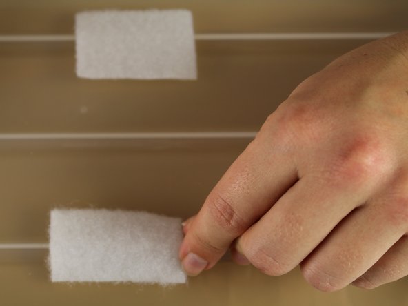
- Open the box and place on a flat, level surface.
- Peel off the plastic from the back of one piece of loop Velcro to expose the adhesive backing.
- Place the piece of loop Velcro in either corner of the box, on the short side that is opposite from where the wires are connected.
- Place the loop Velcro over top the ridge line.
- Peel back another piece of hook Velcro and place on the middle ridge line.
- Peel back the last two pieces of hook Velcro and place in the middle of the box.
- The first piece should go over the top ridge and the second should go over the bottom ridge.
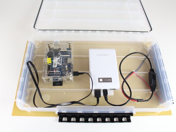
- The box should now look as shown.
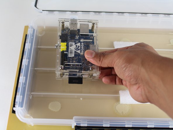
- Place the Banana Pi computer on the set of hook Velcro pieces that are closer together, loop-side down.
- This appears as the left-most set of Velcro pieces in the picture.
- The loop Velcro attached to the battery will be placed down into the box, but first the wires must be attached.
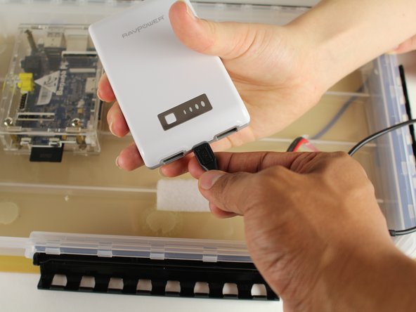
- Insert the voltage regulator wire in the center hole of the battery.
- Insert the USB cord into either of the two USB ports on the battery.
- Place the battery pack down on the hook Velcro inside the box.
- You may have to pull the Banana Pi computer off the Velcro in order to do this step.
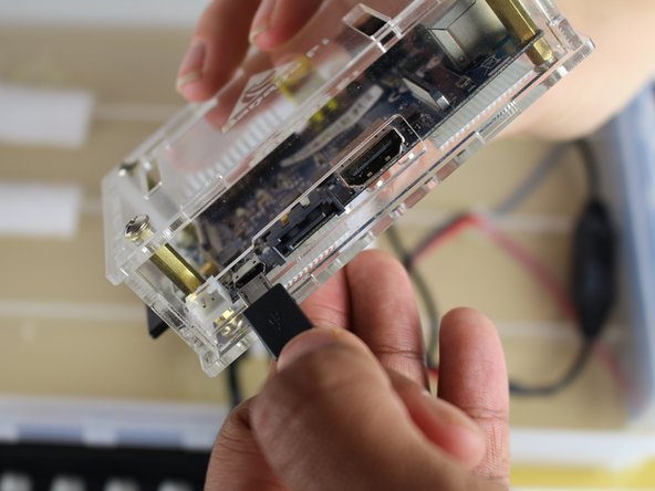
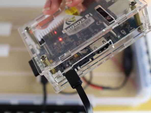
- Locate the mini USB port on the Banana Pi computer.
- This should be on the long edge with the memory card to the left and the WiFi dongle to the right.
- Insert the mini USB plug into this port.
- If the battery is charged, lights on the computer should turn on.
- If the battery was now charged, and the computer did not turn on, the SolarSPELL will have to be taken outside in the sun so that the solar panel can charge the battery.
- Make sure that the SPELL is placed upside down so that the solar panel gets hit with sunlight to charge.